
 Tickets
 Parties
 Shop
Shop Directions
#156 August Status Report
August 31, 2020
With the move of the restaurant to some distance away from the EnterTRAINment Junction (EJ) Upper Aerial Tramway Station, as described in last month’s report, the idea of an elevated walkway from the tram station to an upper floor of the restaurant has become unrealistic.
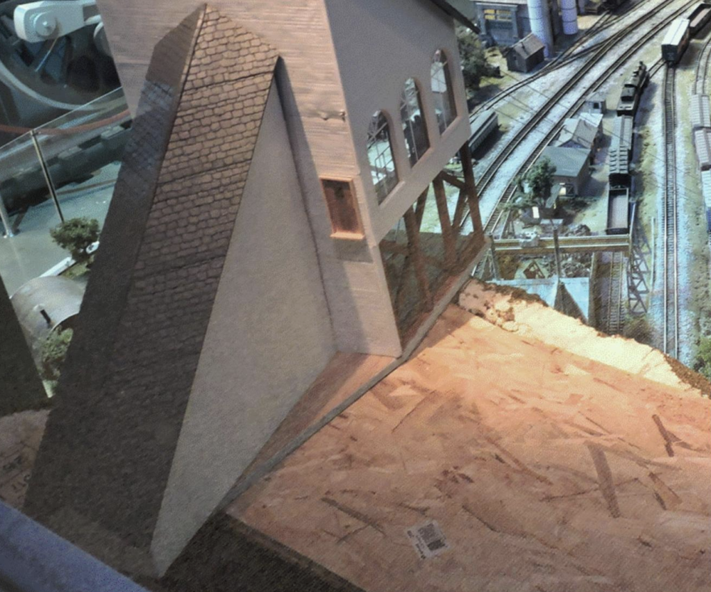
A more realistic solution is that tram customers would ride an elevator between the station platform and ground level. That makes the door at the back of the station, seen in Figure 1, just an emergency exit. However, that also requires the addition of a stairway to get down to ground level. That stairway is the subject of this report. Adding the elevator, on the other hand, would be quite simple. All it requires was the addition of an elevator door at platform level to the central support column inside the station and an access door at ground level in the side of the rear station extension that would lead to the ground-level elevator door inside. Adding a tall stairway, however, is a bit more work.
Building a stairway requires a lot of same-dimension parts properly assembled. The “sawtooth beams” with horizontals on which the stair treads rest would be difficult to make with consistent “teeth” out of single pieces of structural material. Instead, we chose to create the teeth out of constant “height” pieces of wood. The common dimensions for stairs in the US have a 7-inch rise with a 9-inch tread depth. To simulate this using available standard-dimensioned wood, we chose ¼-inch-wide craft sticks for the step height (scale 6 inches) and standard “popsicle” sticks for the treads, which are 3/8 inches wide (scale 9 inches). Stairway width is two inches (4 scale feet). This gave a height to depth angle of 38 degrees (important for setting the angle of the mini-chop-saw used to cut the back ends of the step-height supports). The support beam is ½-inch deep. A set of the height supports and the beam to which they would be attached is shown in Figure 2. Their angled back ends would be forced to line up with the bottom of the beam. Using an appropriate fixture for the chop saw, all of the height supports could be cut to exactly the same length.
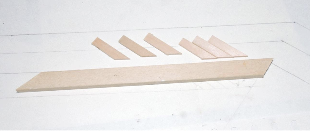
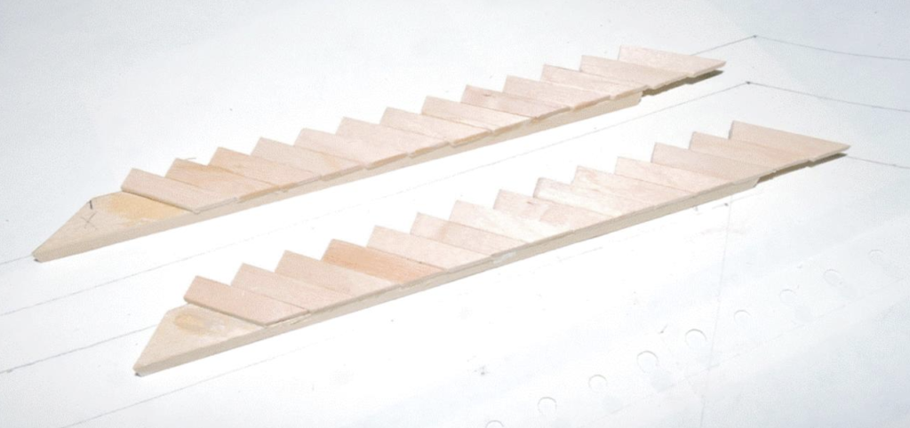
Figure 3 shows the “sawtooth beams” assembled.
Because the station exit door is 8 inches above ground level (that’s 16 scale feet, 32 6-inch-high steps), it was decided that the stairway would have a platform both at its top and in the middle to make it less scary for customers having to use it. Figure 4 shows a collection of the parts needed to assemble the stairway: the four sawtooth beams, four beams to support the platforms, spacers for stair width, some of the stair treads, and some wood to make the platform beams the same thickness as the sawtooth beams.
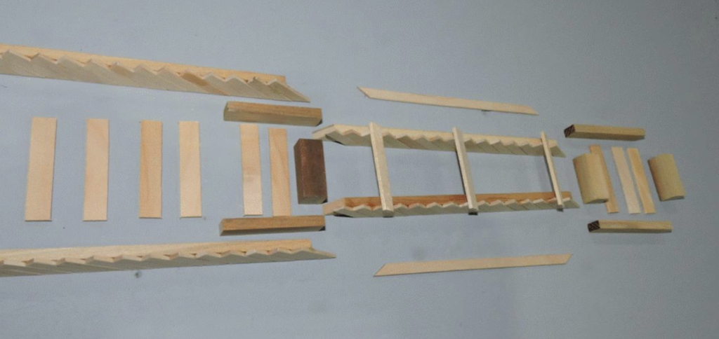
Figure 5 shows the assemble stairway, still missing the platform treads.
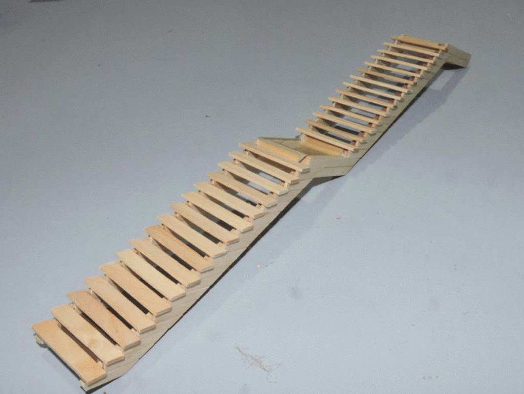
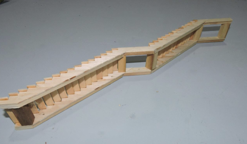
Figure 6 shows a view of the underside of the assembled stairway. Note the holes drilled in the lower sawtooth beams. These are for the screws to attach the stairway to the station extension wall.
Once finished and painted, with a 1/16th -inch wire railing added, the stairway will be screwed to the side of the station extension. The magic of this assembly method is to take advantage of existing consistently-dimensioned materials and appropriate fixturing for cutting parts, like step supports and step treads, to consistent lengths to provide the needed precision of repeating dimensions. Perhaps this method would come in handy for some of your modeling when you need a stairway.
© 2020 Tom Bartsch
MVGRS Big Train Project Coordinator