
 Tickets
 Parties
 Shop
Shop Directions
#152 March Status Report
March 28, 2020
As we transition the EnterTRAINment Junction (EJ) Aerial Tramway from development to operation, the time has come to document the system as it is in its “final” form, primarily so that future maintainers will know not only what it’s supposed to look like, but also why it is the way it is. Saying, “It seemed like a good idea at the time,” won’t help much, so here’s a start to the documentation.
We’ll begin by examining the inner workings of the upper tram station (Figure 1). Its primary purposes are to support the ends of the four track wires and to route the pull of the haulage rope up from one tram car and back down the other. Since the track wires are electrified at 12 volts to supply power for the lights in the tram cars, the two wires in each pair must be insulated from each other. That’s why there are the somewhat complicated plastic and wood insulators, which transfer the track wires’ tension into the upper station’s structure. The bronze clips in the dowels keep the looped ends of the track wires from slipping off the dowels during wire installation or when there is uneven tension during tram maintenance The non-conductive plastic spacer separates the wires, keeps them at the requisite half-inch side-by-side spacing, and transfers the load from the dowel (sized to fit the loops at the end of the wires) to the large s-hook that transfers the load into the station structure.
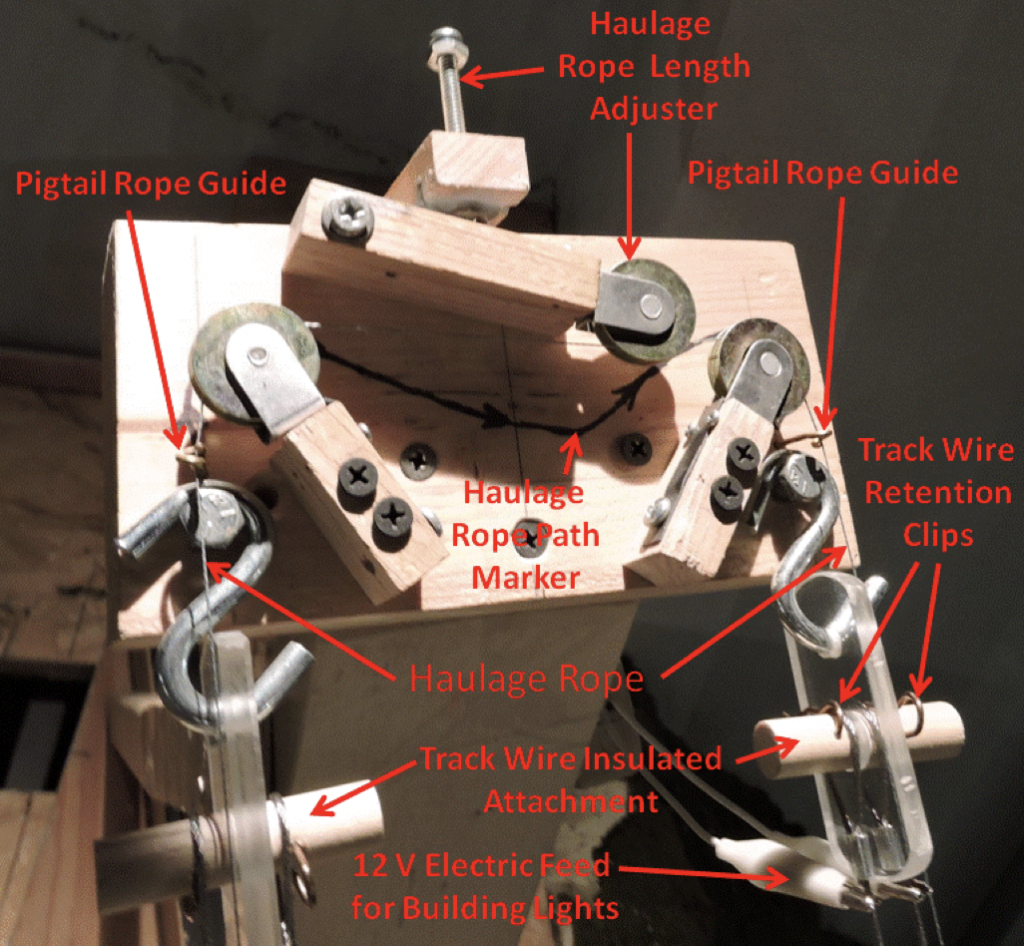
| Figure 1. Upper Station Inner Works |
In order to balance the load from one tram car to the other via the haulage rope, the rope must change direction by 180 degrees. The large diameter pulleys (actually, wheels for sliding screen doors) do this in two steps above each of the tracks plus adding an extra bend around the haulage rope length adjuster. The latter “reduces” the effective length of the upper part of the haulage rope by making it take a detour around the adjuster’s pulley. As the adjusters screw is tightened, it pushes down on the pulley’s lever thus lengthening the detour the rope takes. Being able to adjust the length of the upper part of the rope adjusts where in the upper station the tram car stops. The position of the stop in the lower station is governed by the limit switches, and since the two tram cars are attached to each other via the haulage rope, its length from the top of one car truck to the top of the other car truck fixes where the upper car will stop when the lower one stops. So, shortening the effective length of the upper rope makes the upper car stop at a higher point in the upper station. A benefit from the large diameter of the pulleys is the reduction in internal friction inside the haulage rope’s braid when it is bent around curved surfaces. The sharper the bend, the more the internal friction and the greater the wear will be.
The alligator clips, shown at the lower right in Figure 1, are used to tap
into the voltage available in the track wires and feed that voltage to the lights
in the upper station building. Note that
the clips and wires are not color coded for polarity. This is because the input to the buildings
wiring from the clips is through a bridge rectifier, which converts any
polarity coming from the track wires to the correct polarity needed by the LEDs
that light the building. That means it
doesn’t matter which clip is on which wire.
The routing of the haulage rope is shown by the black path marker shown on the face of the station structure (Figure 1). Note that arrows show the order in which the rope should be strung through the rope guide on the left, around the pulleys, and back through the rope guide on the right. The reason for the specified order is that installing the rope in the guides is sensitive to the starting direction. I’ve only found one way to do it correctly, all others lead to an undesirable tangle. Figure 2 shows an example of a pigtail rope guide (“pigtail” refers to the shape of guide, not to the rope). They have a threefold purpose: to limit the position of the rope within the confines of the inside of its loop, to prevent unwanted escape of the rope (when slack), and to allow the rope to be installed through the loop without needing access to either end of the rope to thread the rope through the loop.
To install the rope in the loop shown in the Figure 2, use the following steps:
1.) Hold the rope on the side of the guide beyond the tip (to the right).
2.) Move the rope to the left side of the shank, with the rope touching the shank.
3.) Move the rope through the slot between the shank side of the loop and the tip counter-clockwise (following the curl of the pigtail from shank to tip).
4.) When the rope exits the slot at the tip, the installation is done.
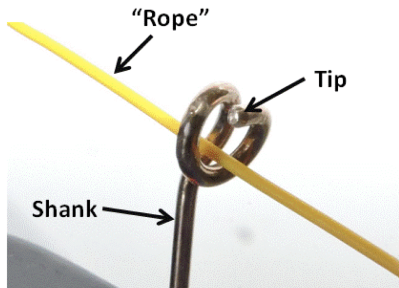
| Figure 2. Pigtail Rope Guide |
To remove the rope from the guide in Figure 2, do the reverse, as follows:
1.) Hold the rope on the side of the guide beyond the tip (to the right).
2.) Move the rope into the slot at the tip.
3.) Move the rope through the slot clockwise (against the direction of the curl).
4.) When the rope exits the slot at the shank,
it’s free of the loop.
The guide in Figure 2 has a right-handed curl, like most common screw threads. (“Right-handed” refers to the common mnemonic of holding the right hand with thumb extended and fingers curled showing the direction of screw or nut motion by the direction the thumb is pointing when the screw or nut is rotated in the direction pointed by the curled fingers.). Guides like this can be made to curl left-handed as well. When installing the rope, always start on the shank side, enter the rope into the slot, rotate in the slot in the direction of the curl. To uninstall, enter rope into the slot at the tip side, rotate in the slot against the direction of the curl.
Pigtail guides can also have more than just the half-loop overlap of the curl like that of the one shown in the Figure 2. The greater the overlap, the less likely it is that the rope will be able to escape due to random motions when the rope is slack. Also, the “shank” does not need to be a straight rod. It could be a loop or hook or whatever mounting configuration is needed to keep the guide in its required position. I’ve used pigtail guides on a number of projects other than the EJ tram with good success. If you find such guides useful for your needs, feel free to make them and use them.
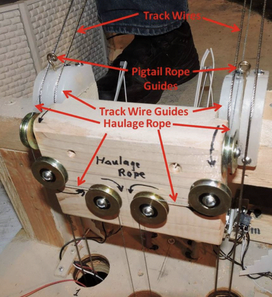
| Figure 3. Lower Station Inner Works (Rear) |
The lower tram station interior has three
functions: direct the track wires and haulage rope from the operating slope of
the tram to the tensioning system below the layout, support the lower end of
the track wires, and stop the tram cars at their “passenger loading”
positions. Figure 3 shows the components
that accomplish the first two of these functions. The track wire guides are “slippery” plastic
(once part of a plastic cutting board) that allow some lengthwise motion of the
track wires as they changes length with changing temperature while their
tension is kept constant by the weights below the layout. The haulage rope is guided to a vertical
direction consistent with the positions of its driving motor and its tensioning-weight
pulley, both also located below the layout.
The front of the lower station is the “decorative” side. This is where there are platforms for passenger loading, interior lighting, and figures of tram customers. The “works” on this side are the two arrays of lever-actuated micro-switches, one array for each tram car (Figure 4). These are all single pole double throw switches which, when actuated open the circuit to one pole and close the circuit to the other pole. Each array has three switches, two of which open the circuit powering the haulage rope motor thereby stopping it; but, because of a special circuit, they only stop it in the downward direction for the tram car that actuates it. This prevents the motor from trying to drive the car farther down the track wire but allows the motor to drive the car back up when the polarity is changed. The third switch closes a circuit to inform the computer control system that the tram car has entered that side of the station. The switches have slotted position adjusters along the direction of the track wires that can be used to set where the cars actuate the switch levers and thereby set how deeply each car enters the station (ideally, to where the bottom of the car door is level with the passenger platform at its side of the station). The two figures and the fake stairs shown in Figure 4 are there to distract long-distance viewers on the EJ mezzanine from paying attention to the rest of the station “features” like the micro-switches or the three “pits of despair” where the track wires and the haulage rope lead downward into the underworld to be stretched on their “racks.”
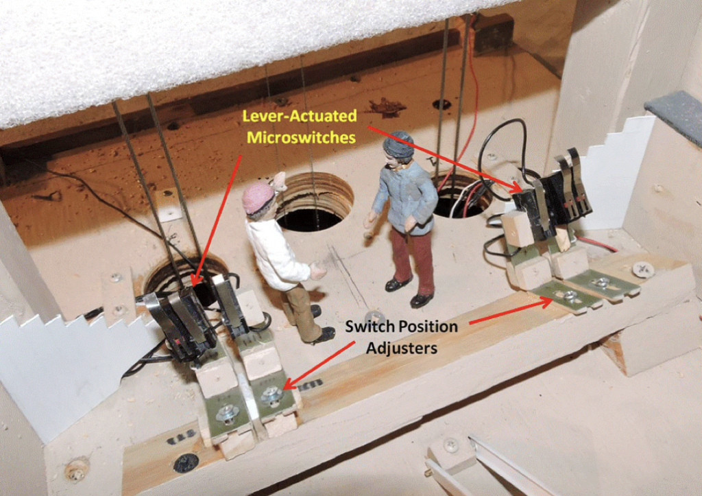
| Figure 4. Lower Station Interior (Front) |
We’ve tried to keep the “works” that are visible to the EJ guests to a minimum so that they don’t detract from the quality of the other modeling. That has forced a lot of the “works” down below the layout. The description of that will be left for a later report. In the meantime, stop by EJ, have a look at the tram, and push the button to see it work. More to come next time.
© 2020 Tom Bartsch
MVGRS Big Train Project Coordinator