
 Tickets
 Parties
 Shop
Shop Directions
#166 August Status Report
August 9, 2021
This month’s report covers some lessons learned from the EnterTRAINment Junction (EJ) Aerial Tram. The tram has been operating reliably for over a year since January 2020. Interestingly enough, it has not been working quite the way it was intended. For all appearances though, it has done what it was supposed to do: start the two cars moving toward their opposite stations at the push of the aisle-side button, travel toward the opposite stations, stop when they arrive, wait until the next button push to move again in the reverse direction to the previous run.
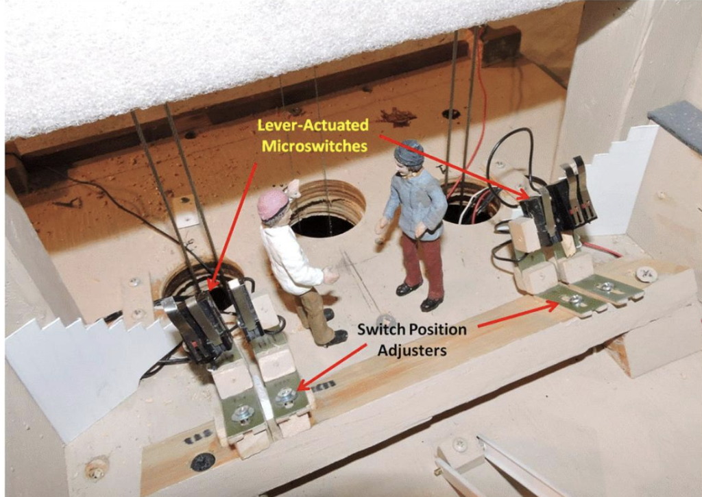
The tram control system design had two primary elements, one electro-mechanical, the other software. The electro-mechanical side had limit micro-switches in the lower station, which would stop the drive motor from driving the bottom-arriving car any farther than the switch, and a micro-switch sensor, which would tell the software the following: that the car was in the station, that the system needed to wait until the next button push, and that the electrical power to the motor needed to have its polarity reversed so that the motor would drive the bottom car back up the run (which would in turn move the other car down the run, since they were connected via the haulage rope). The intent was that the limit switches would never let the motor drive the cars beyond those switches. Figure 1 shows the original micro-switch installation.
The software side was intended to use the actuation of the sensor switch to ramp down the motor voltage to slow the arriving car to a stop in the lower station. The ramp-down was set to take one second. The wait for the button-push and the reversal of motor polarity were handled by the software. In addition, a fail-safe timer would count down during the run and stop the motor and indicate a system fault if the run took longer than the prescribed amount. Finally, the sensor indicating that a car was in the lower station would tell the computer that the system was ready for another run. Because the two micro-switches for each car were lever-actuated, in close proximity, it took much less than one second for the limit switch to be actuated after the arrival sensor was actuated, and the voltage ramp-down had no effect, because the limit switch had already stopped the motor.
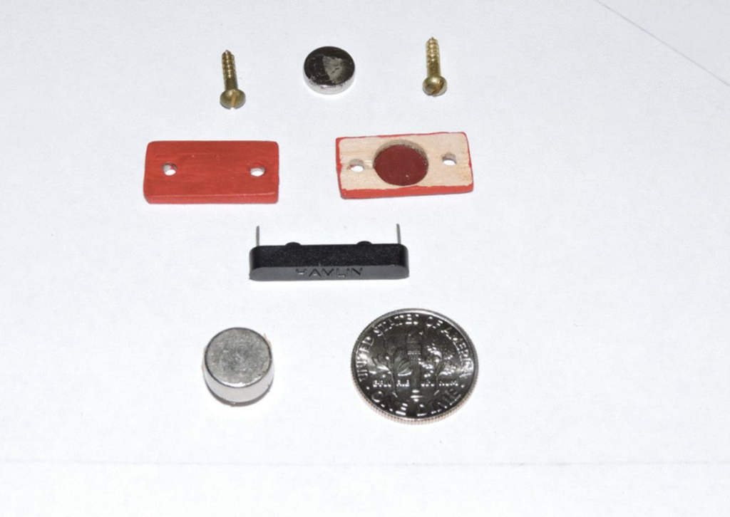
Because some problems developed with the lower station micro-switches in mid-2021, it was decided to explore the use of non-contacting magnetic reed switches for the arrival sensors in the lower station. These types of switches are used throughout the EJ layout to detect the passing and location of trains on the many tracks controlled by the EJ computer. Figure 2 shows the reed switch (black bar), the first button magnet tested on the cars (top), the housings used to install the magnet onto the bottom of the down-track end of the cars, the screws used to attach the housings to the cars (I have no faith in glue under tension, screws are more reliable), the more powerful button magnet (bottom), and a dime to show the scale of all these. The smaller magnets did not have enough range to reliably actuate the switches for the positions needed, so the larger size magnets were installed on the cars, using similarly constructed housings.
The failure to get the small magnets to work prompted the desire to gather some data about where the switch would respond to the magnet. The two parts of Figure 3 are plots of where the switch actuates and stays actuated as the magnet approaches the switch. The diagonal line in each part of the figure shows the potential path that the magnet should take into and through the actuation zone to maximize the distance over which the switch is actuated. This is shown for two different orientations of the sensor. The orientation on the right looks like the more effective. Oddly, the data show that passing the end of the sensor works far better than approaching it near its center, where the sensor’s magnetic metal leads appear to interfere with the magnetic field’s ability to actuate the sensor. It also shows that angling the sensor perpendicular to the magnet’s path actuates the sensor over a greater distance.
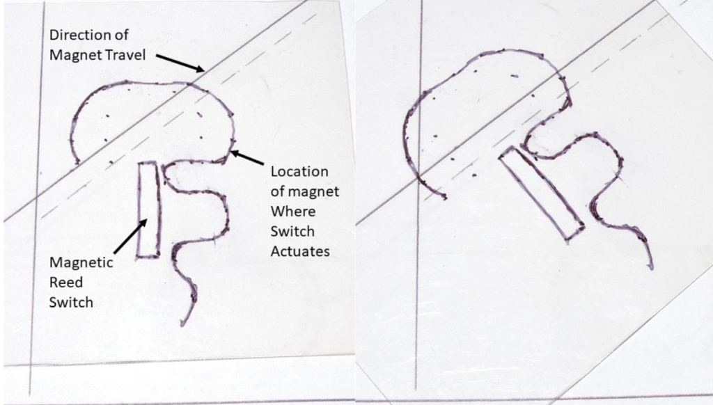
Figure 4 shows the front and back of the brackets used to hold the reed switches in place, at an angle as suggested by the sensor activation data shown above. The sensor is soldered to the section of circuit board, which is bolted to a fiberglass extension that is bolted to the aluminum bracket, which is screwed onto the base of the lower station. Note the slot in the fiberglass extension, which allows some height adjustment. Since the sensor is mounted underneath the descending path of the car, most of the height adjustment relative to the car can be handled by moving the sensor along the car’s path and checking its responses to the car passing before the bracket is screwed in place on the base.
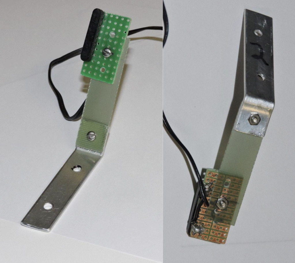
Figure 5 shows the tram car at its lower limit, where it contacts the padding between it and the station structure. At this point the limit switch at the left is fully actuated. Note the magnet housing extending from the base of the car. Although it looks like the housing would contact the sensor, the path of the car is angled upward enough so that it does not.
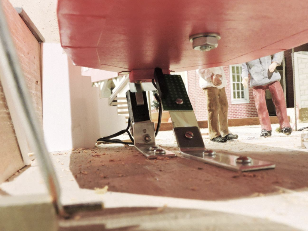
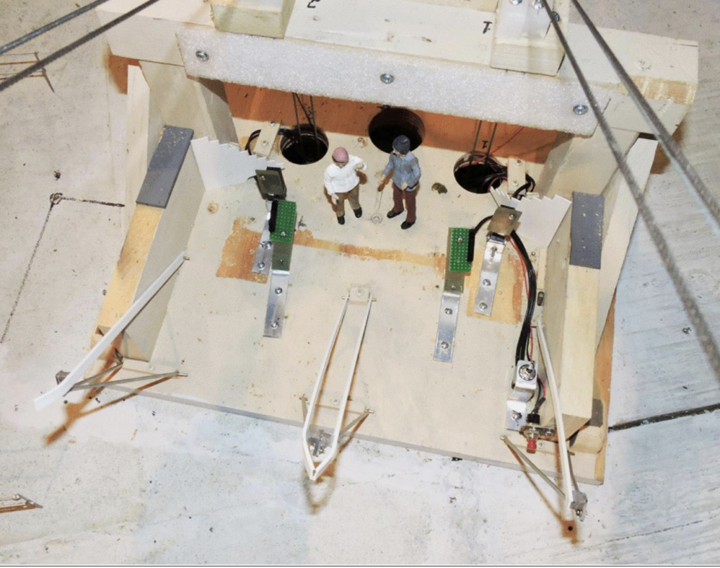
Figure 6 shows a top view of the sensor installation in the lower station. The reed switches on their green circuit boards toward the center are actually centered below the track wires, so that the magnets pass directly over the sensor ends. The limit switches, with their broad paddles are behind and to the outside of the sensors. The reed switches were positioned in such a way that they would still be actuated should the car travel to the point of touching the padding on the cross-beam supporting the track wire pairs (shown at an angle across the top corners of the figure). In case you’re curious, the large hole in the center routes the haulage rope down to the motor and the rope tensioner. The two holes on either side route the track wires down to their tensioning system.
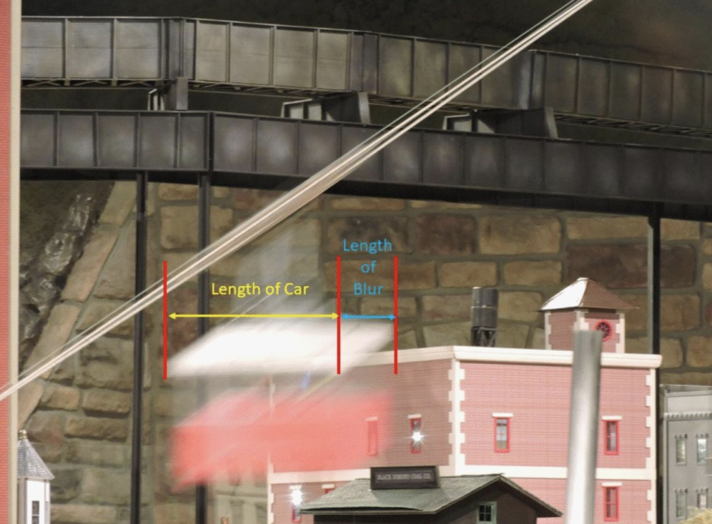
One final question that needed to be answered is how far does the car move horizontally in one second? How to find out? Take a one-second-long exposure (Figure 7) while the car is underway and measure the horizontal “length” of the blur divided by the car’s length in the image, multiply the result by the car’s actual length (7 inches), and you have the answer: about 2¼ inches.
So, the lessons: 1) If you use software to control some electro-mechanical system, know all of what the software is doing to and for it. 2) Don’t assume something will work, if some appropriate measurements will tell you for sure one way or the other. 3) The more places there are for something to go wrong, the more likely it is that something will. Murphy’s Law and the KISS principle (Keep it Simple, Stupid) are reinforced yet again.
With luck, the new fixes will keep the tram up and running for much longer than another year.
© August 2021 Tom Bartsch
MVGRS Big Train Project Coordinator