
 Tickets
 Parties
 Shop
Shop Directions
#150 January Status Report
January 24, 2020
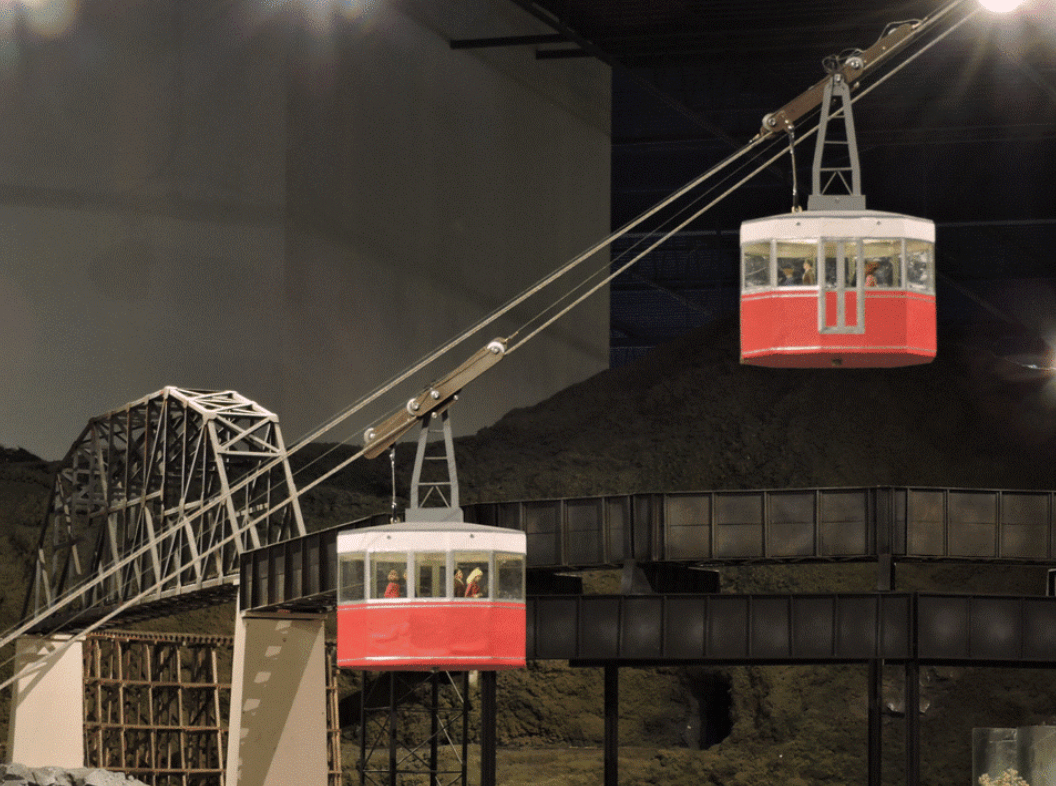
The EnterTRAINment Junction (EJ) Aerial Tramway has at last been installed on the EJ layout! While more remains to be done to make it work, Figure 1 is very close to how the tramway will look when it’s fully operational.
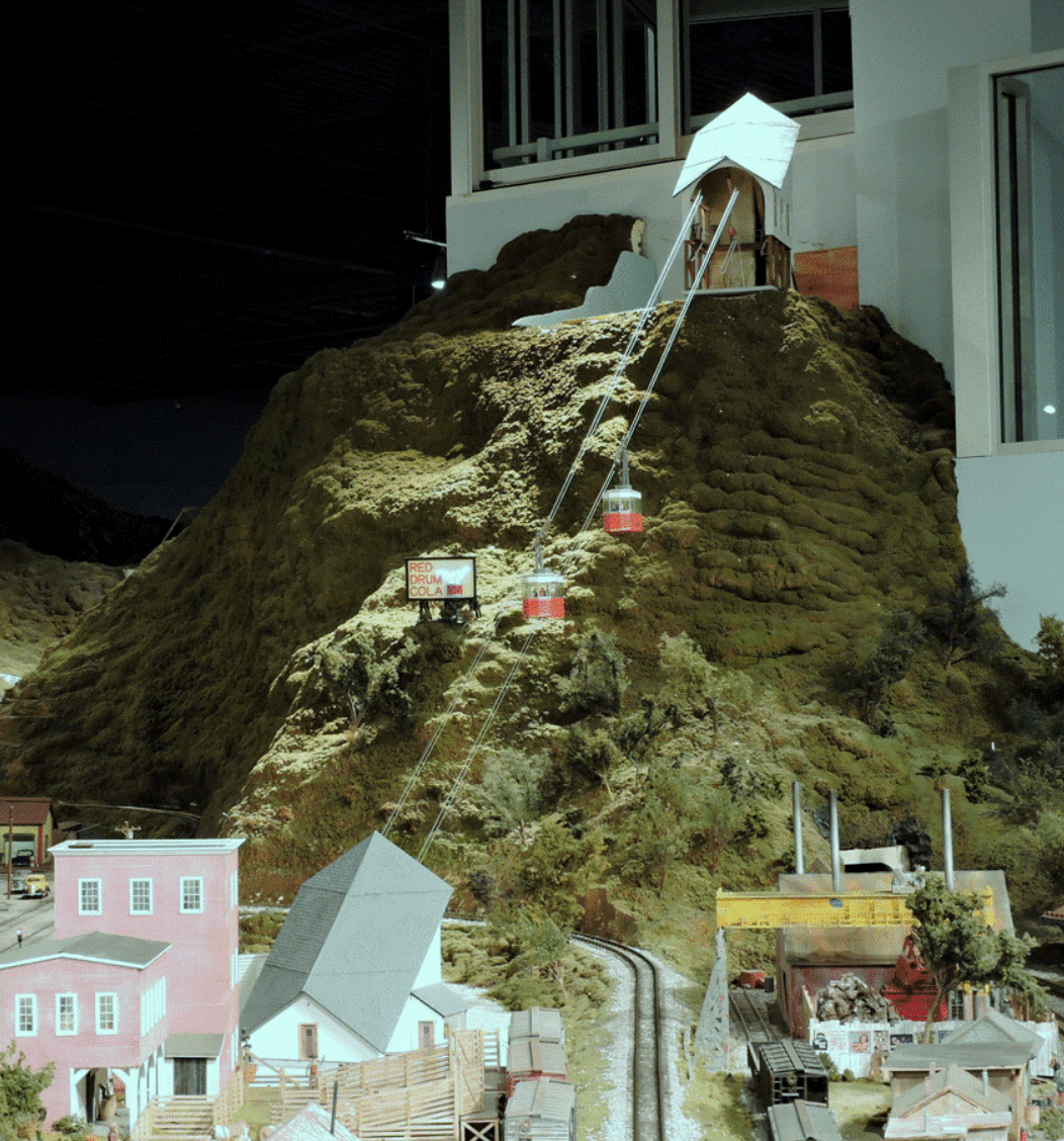 |
| Figure 1. Aerial Tram Installed |
The first step in the tram installation process was to prepare the surface of the lower station area and make room for its stairway and access road. The surface of the “meadow” had ground-foam “grass,” which needed to be scraped off and vacuumed away. The meadow area was then painted a color representing crushed granite gravel for the tram parking lot and surroundings, differentiating it from the concrete color of the upper-level streets and from the simulated asphalt of the tram access road. In order to leave enough room for the tram station and its parking lot, the access road needed to curve 90 degrees and run parallel to the upper level road as it sloped down to the meadow level. Making room for this configuration required cutting back some of the scenery that transitioned the layout from its lower level to its upper level in the area adjacent to the stockyard building. The stockyard building is the one on the lower level at the far left of Figure 2. The results of the surgery on the scenery are shown in Figure 2
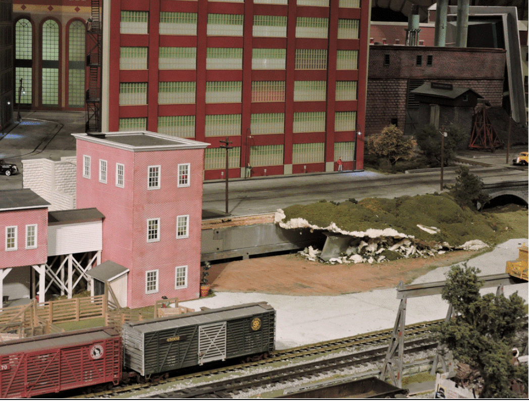 |
| Figure 2. Layout Surgery for the Aerial Tramway |
In order to fit everything together snugly, installation began with the access stairway and the two retaining wall sections on either side of it. The retaining wall at the far side of the stairs (as viewed in Figure 3) was mated to the stockyard building, then the access road with its retaining wall was mated to the retaining wall on the near side of the stairway. The original plan was to mount the cut edge of the remaining scenery on top of the edge of the access road, but the thickness of the remaining scenery made it easier and better looking to put the edge of the scenery underneath the edge of the road. There were a few areas where the scenery foam was too thick to fit well under the road, so these had a groove carved into the foam to hold it at the desired height by the edge of the road. The stairway and road were anchored to the layout table with screws going upward through the layout table from below into structural parts of the stairs and into the road supports.
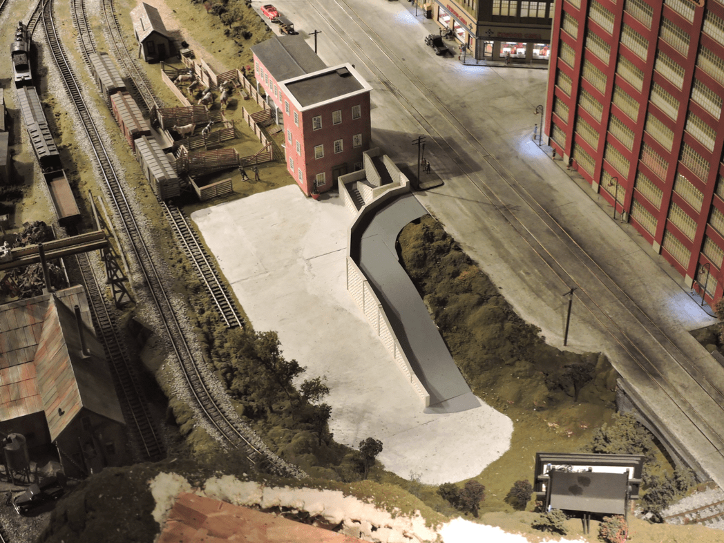 |
| Figure 3. Lower Station Parking Lot Access Road and Access Stairway |
The end of the meadow closest to the stockyard building had the most amount of room for accommodating the lower tram station. A cardboard template representing the base of the lower station, with a marked centerline and cutout holes where holes in the table were needed, was used to set the position of the station, align its centerline with the upper station’s centerline, and position the holes in the layout table for the track wires, which would be tensioned below the layout, and the haulage rope, which would be driven by a motor mounted below the layout. The positions of the aligned station base and the holes were marked on the layout table, the cardboard was removed, and the holes were cut in the table at the marked locations with a hole saw.
Meanwhile the position and alignment of the upper station was determined using a plywood replica of the upper station’s base. The replica was placed with its front left corner at the edge of the shelf on which the station was to be located. The replica had a vertical board mounted to it aligned with the upper station’s centerline. Sighting along the centerline side of the board and aiming it at and aligning it with the lower station centerline set the direction of the upper station. The vertical board was also the sighting target for aligning the lower station. The replica also had a fixture at its right front corner for measuring the length and angle needed for a gusset that would look like it supported that corner of the base and was anchored into the hillside (cosmetic structure).
Once the replica was properly aligned, the position of the station was marked on the shelf, and the position and direction of the access hole in the shelf were measured and marked on the replica. These measurements were used to construct the station’s rear mounting beam. The hole in the shelf, shown at the lower left of Figure 4 next to the rear extension of the station, was there to allow installation of the station’s rear mounting beam below the horizontal shelf beams which run perpendicular to the shelf’s outer edge. That mounting beam would be bolted to the station’s rear horizontal support with a long vertical threaded rod, which had been firmly attached to the mounting beam. This would firmly, clamp the station base to the supporting beams. That configuration was needed to ensure reliable transfer the tension loads from the track wires through the station base’s into the shelf structure. It made the transfer of the loads independent of how well the shelf board itself was mounted to its supporting beams.
 |
| Figure 4. Tram Stations Installed |
Each station base was mounted via a single screw through the base centerline around which fine adjustments to the station’s alignment could be made. A second screw elsewhere through the lower station base into the layout table fixed the direction of that station. The bolted support beam fixed the direction of the upper station. The fixing of the upper station alignment by the support beam would later be augmented by an additional screw through the base into the shelf board.
To determine the length of the four track wires from which the cars would hang, a string was attached to the upper station’s wire-mounting insulator and the other end of the string was passed from the shelf to a team member on the layout table via a 12-foot long crappie (pronounced “croppy”) fishing pole. The distance to the lower station wire support was marked on the string, and that length, plus the additional length needed to attach the wire to the tensioning system below the table, was used to cut the four track wires to length. One wire of each pair was cut shorter to accommodate a turnbuckle that would be used to balance the tensions of the two wires in each track set. Loops were swaged into both ends of all four of the wires for attaching the wires to the system. Each wire was attached to the its respective upper station wire insulator and the other end was passed via the crappie pole to the team member on the table for insertion through its hole in the table for attachment to a temporary weight which would keep it in place under some tension. Next, the haulage rope, a little more than twice the length of the longest track wire, had its ends tied together to form one large continuous loop. One part of the loop was installed through the upper station’s haulage rope guides and around the length-adjustment pulleys. The other end of the loop was passed, via the crappie pole, to the team member on the layout and installed through the guides in the lower station, around its pulley set, and then, with a weight attached, through its hole in the table. With all the lines tensioned under the table with weights, the lines spanned the distance between stations without sagging onto the layout. The removable station buildings were then installed over their respective base plates, and further installation was left for a subsequent work session (Figure 5).
 |
| Figure 5. Initial View of the Installed Stations |
The next step in the installation was to install the track wire tensioning system. The half-gallon milk bottles, partially filled with water, which had been used as tensioning weights on the test fixture, were weighed, emptied, dried, and filled with sand to the same weight (about 2½ pounds). The lever system, which multiplied the tension of the weights by a factor of five, was installed under the layout and temporarily wedged in place with shims. It would later be screwed into the layout table above and into the concrete floor below. The track wires were attached to their respective insulators, and those were hooked to the tensioning levers. The weights were then hung on the ends of the levers, making the tension now about the same as it was on the test fixture. Next, upper and lower hooks, for attaching the cars to the haulage rope, were installed on the haulage rope. The attachment method left the rope continuous, but also gave a bit of slack in the rope as it passed between the upper and lower hooks when they were attached to the car’s truck. This would allow removal of the cars without a break in the haulage rope. The cars were installed on the wires and the haulage rope was hooked to the car trucks both front and back. Because the track wires were at a slightly different angle than on the test fixture, the cars’ damping struts had to be adjusted so that the cars would hang straight down with their floors level (Fighre 6).
 |
| Figure 6. Tram Cars Installed on the Track Wires |
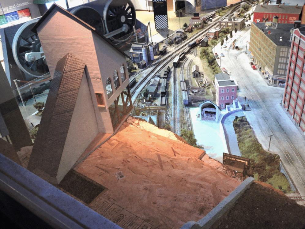
With that part of the installation complete, it left the tram in a static position, but looking very much like it would appear on part of its run once it was fully functional (Figure 7). That would allow EJ visitors to enjoy it over the Christmas 2019 holidays and, hopefully, motivate them to come back to see it in operation in the future.
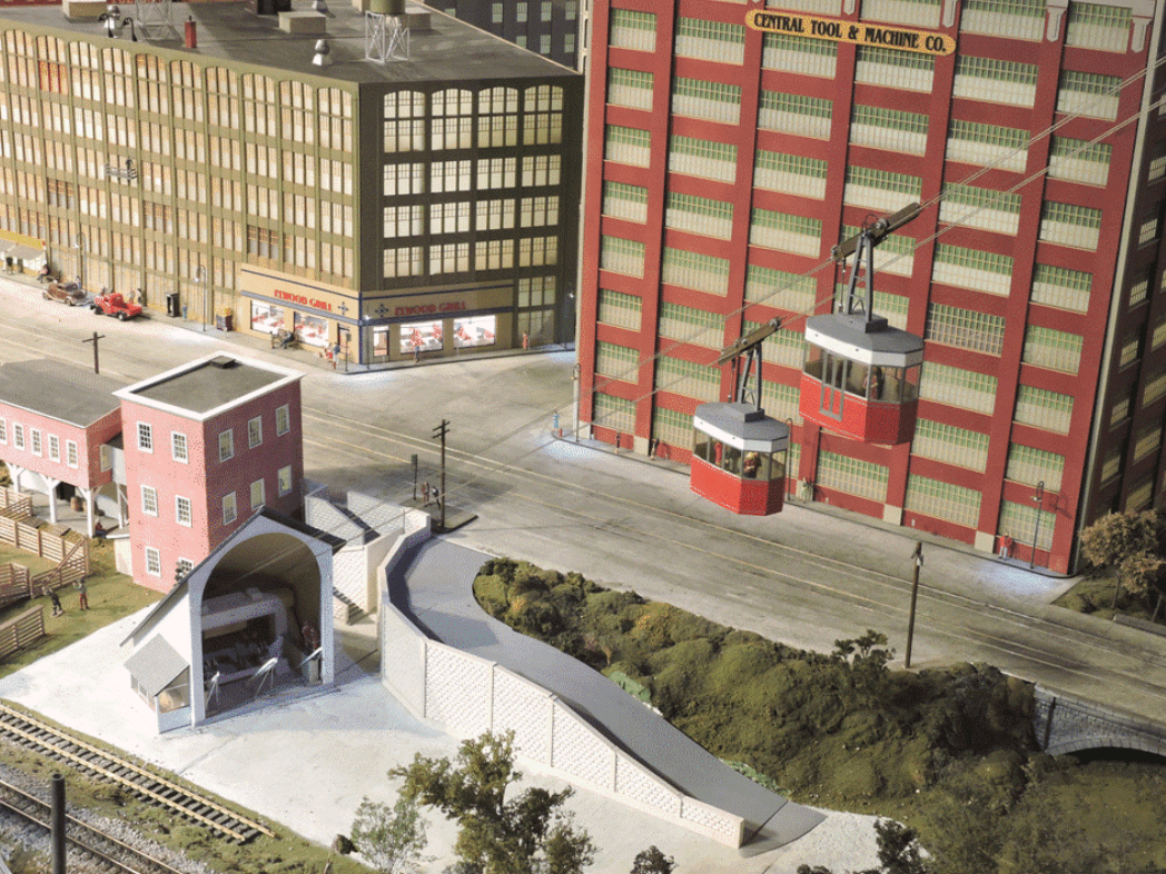 |
| Figure 7. View of the Tram from the Landing on the Mezzanine Stairway |
There is, of course, much more work yet to be done. The lighting on the stairway and buildings must be installed; wiring for the lighting must be hooked up; the haulage rope motor must be installed and wired to the controller; the system must be tested; the control scheme must be programmed; a button to activate it must be provide on the layout aisle; and additional decorative items need to be added, like fences, parked cars, and, of course the piece de resistance, the restaurant next to the upper station that is the reason for the tram’s existence. So, with this major milestone accomplished, it brings us to new challenges, many of which are related to the much more limited accessibility of the tram components. The story is far from complete, but the work on it remains enjoyable in the doing, and we will get it done.
For now, I wish all my readers the best for the new year.
© 2020 Tom Bartsch
MVGRS Big Train Project Coordinator