#165 July Status Report
July 15, 2021
The Big Train Project Status Report (Part 165)
This month’s report is a bit unusual in that it is multi-purpose. First, it addresses some maintenance issues with EnterTRAINment Junction’s (EJ’s) Aerial Tram. Second it documents the method for installing and removing the hooks that attach the Tram’s haulage rope to the Tram car trucks for when future maintenance is required. Third, it shows a scheme for attaching hooks or loops onto a continuous rope, without breaking the rope, that will hold the hook or loop in place under tension from either end of the rope without slipping, and do so in a way that will allow the hook or loop to be easily removed. This scheme is readily scalable to both smaller and larger applications, should one choose to use it. I have successfully used it at a smaller scale on a model sailboat, and have tested it successfully with larger rope diameters and loop sizes as well. A common caution applies: “not for use in climbing.”
The reason for this invention was the need to replace the haulage rope on EJ’s Aerial Tram. After over a year of successful operation, some issues developed which generated some excessive wear on the haulage rope from slipping at the drive motor pulley. In order to most easily replace the haulage rope, it was decided to use the old rope to pull the new rope around and through all the pulleys and guides that are part of the Tram’s haulage rope system. That meant removing the old hooks, so that they would not get caught on those pulleys and guides during the haul-around. The previous hook design (Figure 1), described in Report 151, turned out to be more difficult to remove than anticipated, and two of the four hooks had to be cut out of the old haulage rope in order to remove them in a timely fashion. The difficultly in removing the hooks and the potential for hook slippage, if the installation was not done exactly correctly, motivated a change in the hook design.
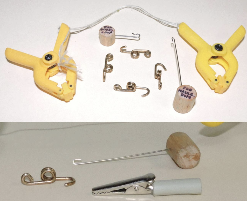
The new design hooks, first used on the sailboat model mentioned earlier, are the bronze-colored items shown in Figure 2. They have the hook at one end, two coils in the center, and a loop at the other end. The loop has no function during rope operation, but the loop does blunt that end and it provide a place for the holding tool (upper center of Figure 2) to keep the hook captured during removal. Being a butter-fingered person myself, I’m sure I would drop and lose the hook if I didn’t have the help from that tool. The string-connected clamps are used to hold some slack in the haulage rope during hook installation and hook removal. The tool with the long wire hook is for manipulating the haulage rope. The alligator clip with the grey handle is for holding the hook to the desired location on the haulage rope during installation. The jaws of the clip have rubber pads between the teeth of each jaw to provide the needed friction to hold rope and hook in place. The handle is round to allow it to be rotated along its lengthwise axis with the fingers of one hand.
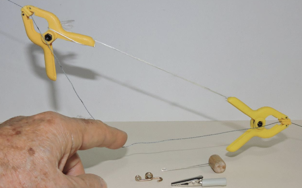
For hook installation, it is imperative that the haulage rope tension be reduced by replacing the normal tensioning weight with one of considerably lower weight, otherwise, the clamps will not be able to hold the slack needed for the installation. The hooks each require 1+3/8 inches of haulage rope when tight, and there needs to be some more slack to allow the necessary manipulation (Figure 3). Hook orientation matters. The upper hook for each tram car must have its hook at the downward end, and vice versa for the lower hook. The knot where the two ends of the haulage rope are connected forming a continuous loop, should be near the middle of the slack in the rope that will end up between the upper and lower hooks (preferably for Car No. 1) to avoid tensioning the knot when the system is operating. The location of the hooks for Car No. 1 should be determined first, then the hooks for Car No. 2 so that both cars are in opposite stations at the end of each run. The determiner of the cars’ relative location in the stations is the length of the haulage rope between the cars’ upper hooks. .It is probably wisest to install all four hooks on the haulage rope before hanging each car on the track wires and then connecting its hooks to the truck, top hook first
The magic of the non-slip scheme on the rope is provided by the coils on the hook. Only one coil is needed to keep the rope from slipping, but the second coil provides a convenient groove between the two coils that makes it easier to get the manipulator hook under the desired part of the haulage rope when it’s time for hook removal.
Figure 4 shows the sequence for installing the hook. The haulage rope is marked where on the rope the hook end should be located, and the clip holds the rope to the hook end there. Then the process is to pull a loop of haulage rope through the coils, around the “back” of the hook and then over the coils on the front. Since this path is more than once-around the hook, it’s easier to rotate the hook (using the clip) than trying to move the manipulator hook all the way around the haulage hook. The reason for all of the slack required in the haulage rope is that some of that (from the left in Figure 4) is used for the rope loop and some of it (from the right in Figure 4) is wound around the clip during rotation (Figure 4d and e and Figure 5).
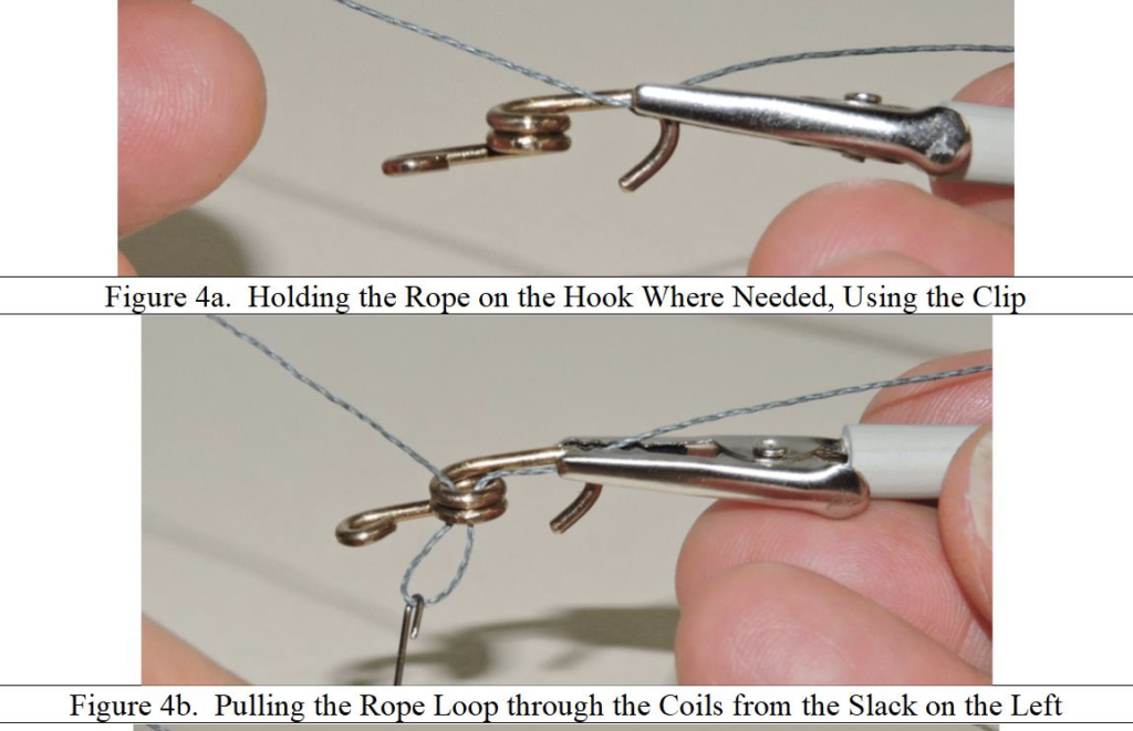
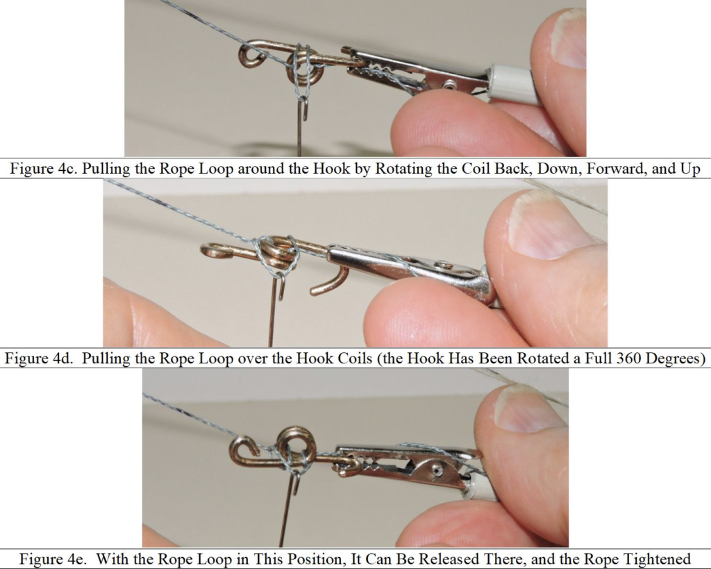
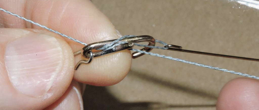
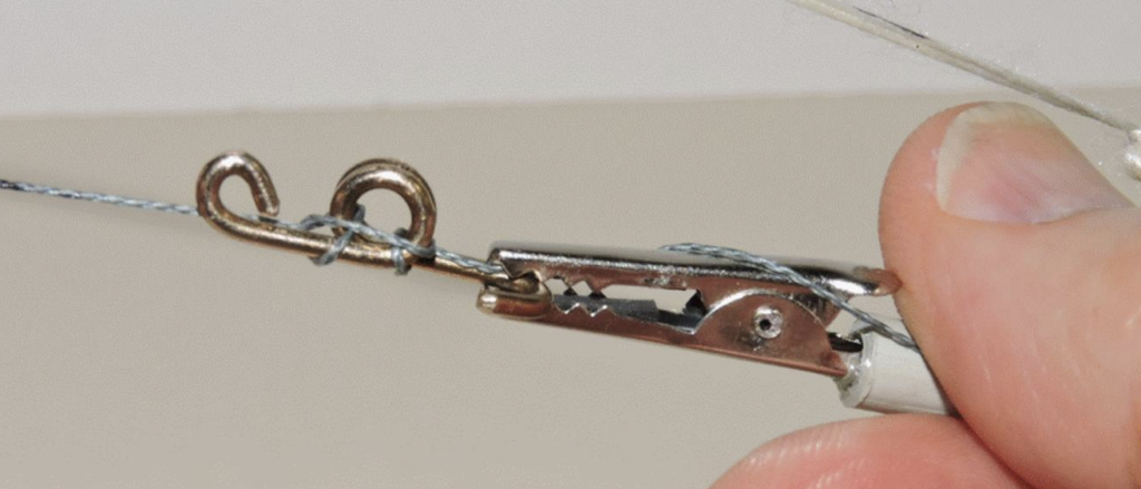
Figure 5 shows the completed installation. Note the rope loop running across the front of the coils and the rope wound around the clip due to the clip rotation.
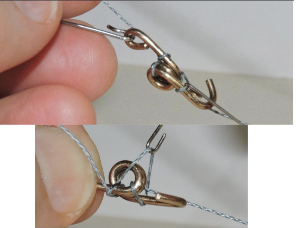
That’s it for the installation, but what about the removal? Again, the rope tension needs to be reduced and the connected clamps applied to provide some slack, but not nearly as much as for the installation. For removal, the objective is to get the loop in the rope back off over the coils. With that done, the rope pulls out easily. This operation is where the holding tool is critical (Figure 6). While it is possible to wrestle the rope loop off of the coils, it’s easier to loosen it first by pulling some slack into a portion of the rope that crosses the “back” of the hook as shown in the top image of Figure 6. Then hook the manipulator into the loop going in front of the coils and pull it up and over the top of the coils as shown in the lower image of Figure 6. Unhook the manipulator tool, and the holding tool will prevent the hook from getting away (as long as you keep hold of it) as the haulage rope loop pulls out through the coils.
This system will work with any kind of “ends” on the “hook” as long as there are some extensions that go beyond the coil (or coils) on both sides, and as long as the “hook” is stiff enough throughout its structure to retain its shape under whatever load is applied to it and the rope. Needless to say, it’s much easier to use of larger scale ropes and loops that don’t require the use of the tools.
If you have a use for this technique, feel free to use it.
© 4 July 2021 Tom Bartsch
MVGRS Big Train Project Coordinator

 Tickets
 Parties
 Shop
Shop Directions