
 Tickets
 Parties
 Shop
Shop Directions
#151 February Status Report
February 11, 2020
The EnterTRAINment Junction (EJ) Aerial Tramway has at last been functionally tested on the layout, and by the time you read this, it should be hooked up to the EJ computer control system and functional for visitors to operate at the touch of a button (which has also already been installed). Like many systems that move from test setups to their operational installations, the tramway came with some surprises. Those are the subject of this report.
The first surprise was discovered while trying to install the track wire tensioning system. The struts that positioned the levers between the floor of the building and the underside of the layout table could not be wedged into place. They seemed to be too long, despite being cut 1/8 inch shorter that the measured distance. When the team member on top of the layout table moved away from the lower station on the table, the struts were easily positioned, wedged into place with shims, and later screwed into the table and into the floor. The lesson, the seemingly-solid layout table flexed more than expected under the weight of a person.
When the wiring for the 12-volt lighting of the tram cars and the two stations was hooked up and checked out, the lights seemed unusually dim compared to what they had been on the test fixture. A bit of sleuthing with a volt meter determined that they were only getting 9 volts. Replacing the power supply cured the problem, as seen in Figure 1, with lighting in the stations and in the cars readily visible.
Figure 1. Aerial Tram Car and Station Lighting
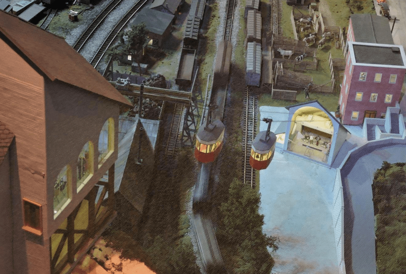
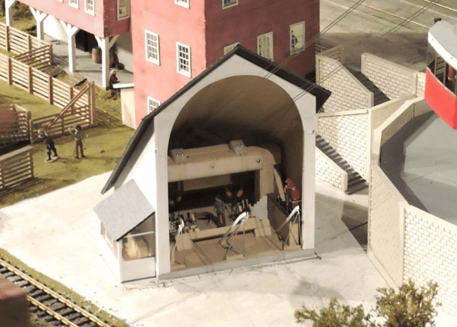
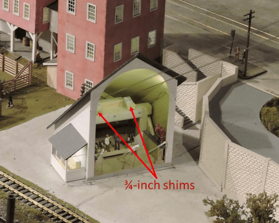
When we checked out the alignment of the lower station by running the cars to their docked positions, we found that the direction was fine, but that the height of the car was too low to make proper contact with the limit switches which were supposed to automatically stop the car at the docked position. That was due to the shallower angle of the track wires, compared to the angle was in the test fixture. Though the track wires were at the same tension, the difference in the angle of the direct sight line between the cable mountings in the two stations of about three degrees and the different wire angle due to sag from the weight of the cars over the longer span of the wires were enough to lower the cars below the adjustment range of the limit switches. The solution was to put a ¾-inch shim under the wire supports in the lower station, thus raising the wire by that amount, sufficient to let the cars properly contact their limit switches.
Figure 2. Revised Lower Station Track Wire Supports
In the installation, we changed the manner in which the haulage rope was connected. In the test rig, there were two separate haulage ropes, an upper – connecting the upper ends of the car trucks via the upper station pulleys – and a lower – connecting the lower ends of the car trucks via the lower station pulley system, the motor, and the haulage rope tensioning weight. The connections between the two were the car trucks. This method ran the risk that while installing the hook at the end of the upper haulage rope to the truck, the rope might be let go by accident, the haulage rope then might have to be restrung, or much worse, there could be a runaway car if the other car was already hooked up to the other end of the rope.
To prevent this, the on-layout installation used a single haulage rope, made continuous by a single knot, which was located between the front and rear hooks on one of the cars. In that location, the knot would never run through either pulley system, where it could tangle or increase rope wear. The challenge then was how to install the hooks on this continuous haulage rope without a break in the rope, without the hooks slipping along the rope, and with having their positions adjustable so that the locations of the cars in the stations could be fine tuned.
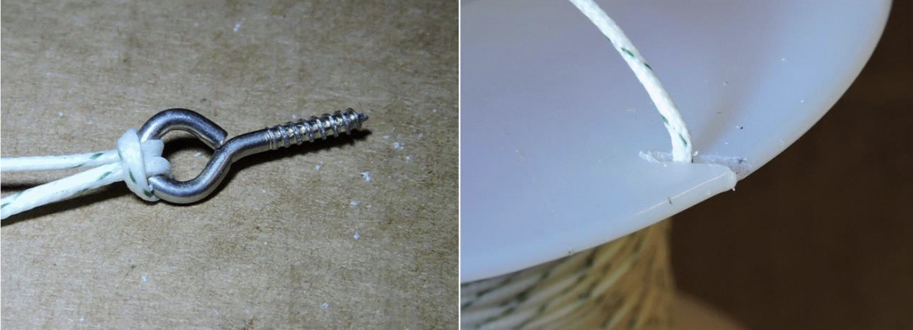
The situation reminded me of the old rope puzzle shown on the left in Figure 3 – how do you remove the rope from the eyelet without letting go of the ends of the rope, without cutting the rope, and without opening the eyelet? The answer: pass the eyelet through the loop in the rope. It also reminded me of how to anchor the end of fishing line or thread on spools – cut a notch and wedge the line into the notch (Figure 3, right).
Figure 3. Rope Tricks
So, the answer was to pass a loop of the haulage rope through an “eyelet” on the hook used to attach the haulage rope to the tram car truck, then to pass the loop around the hook, and finally to wedge the loop into a notch on that hook so it wouldn’t slip. Simple? Yes, but only if it’s done right, and there are lots of ways to do it wrong, and the rope will slip, thereby moving the hook to where it shouldn’t be (as I learned from experience).
Experience also taught me that holding the hook with fingers or with pliers, while trying to pass a loop under tension through a tiny eyelet, would easily lose the grip on the hook, potentially sending it flying (and if on the layout, probably never to be seen again). So we developed three tools to help with the task: one to release the tension on the portion of the haulage rope where the hook was to be installed, one to hold onto the hook so that it could not escape, and one to manipulate the haulage rope loop (Figure 4, top, middle, and bottom, respectively). The bottom figure shows relative sizes. The handle in the middle picture is a piece of 3/8-inch dowel.
Figure 4. Haulage Rope Hook Tools
The critical piece of the operation is the orientation of the haulage rope loop when it is placed over the hook end of the hook (Figure 5). In the figure, the hook is pointed backwards from its final position. The hook end is toward what will be the tight end of the haulage rope, which in the figure is on the right, as the loop is being pulled down over the hook end.
Figure 5. Hook Installation on the Haulage Rope
Once the loop is over the hook end, the loop can be released and the ends of the haulage rope can be pulled tight. Then the hook can be turned toward the slack end of the haulage rope and the joint tested by pulling tightly on the tight end while leaving the slack end slack. If the haulage rope doesn’t slip in the hook, the installation is a success. Figure 6 shows the hook being tested, with the tight end on the right, the slack end going up to the left. The notch that holds the rope in place is to the left of where the eyelet extension crosses the hook’s shank. On this hook that crossing was soldered on the eyelet side of the crossing so that the rope could not force the joint open. However, the notch to the left needed to have a sharp angle at its bottom (no solder fillet) to ensure that the rope would wedge itself into the notch tightly.
Figure 6. Hook Installation Being Tested
It turns out that because of the rather simple path that the rope takes, it is fairly easy to loosen the wedging and then move the hook to another location along the haulage rope. So, what was the surprise? All three objectives – no break in the haulage rope, no slippage along the rope, and adjustability – were all achieved with such a mechanically simple device.
After the struggles I had in getting the technique right, the challenge now is to provide adequate and understandable instructions in the EJ Aerial Tramway Maintenance Manual on how to do this installation correctly consistently. Though it is highly unlikely to need to be done very often, there will come times when the haulage rope breaks or will need to be replaced due to wear, and that’s when the instructions become extremely important. Who knows if I’ll still be around to do it, and even if I am, I’m not likely to remember the fine points of how it’s done.
The thought of the haulage rope breaking brings to mind the unpleasant potential impact of that failure – runaway cars smashing into the lower station. The station would survive, but the cars probably wouldn’t. So here’s a new challenge: how to slow or stop the cars on the wires in the event of a haulage rope failure above the cars. Looks like we’re not done yet. There will be more to come. Stay tuned.
© 2020 Tom Bartsch
MVGRS Big Train Project Coordinator