
 Tickets
 Parties
 Shop
Shop Directions
#147 October Status Report
October 28, 2019
This month’s report describes the work underway to provide lighting for customers of EnterTRAINment Junction (EJ) aerial tram on the paths to the tram stations. After constructing the stairway described in Report Number 146, the Tram Project Team realized that the restaurant, which the tram serves, would very likely operate beyond just the daylight hours. That would make it necessary to provide lighting for the customers’ safe passage to and from the stations.
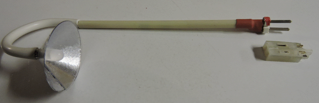
As with all of the lighting that the Team has done for the EJ layout, LEDs were the lights of choice; however using the usual three-LED strips did not seem appropriate in this application for the late 1940’s time period. That meant using single warm white LEDs to simulate the incandescent lighting of the period. This required the use of a resistor in the circuit for each LED, to reduce the current to the 3-volt LEDs provided by the EJ’s standard 12-volt power supplies used for lighting. The chosen resistance needed to be sufficiently high so that the resistor(s) would not get excessively hot when run for long periods of time, but low enough that the lights would still have realistic brightness. We chose to use two 470 Ohm resistors in series (because these resistors were packaged with the LEDs we purchased). The design of the light fixtures needed to be simple enough to allow us to easily make multiple matching copies that would also be consistent with the 1940s time period. We chose a conical shade attached to a bent-pipe support (Figure 1). Also, the fixture needed to be removable to avoid damage during station installation and to allow maintenance or repair if required in the future. A fairly solid plug and socket design satisfied that need.
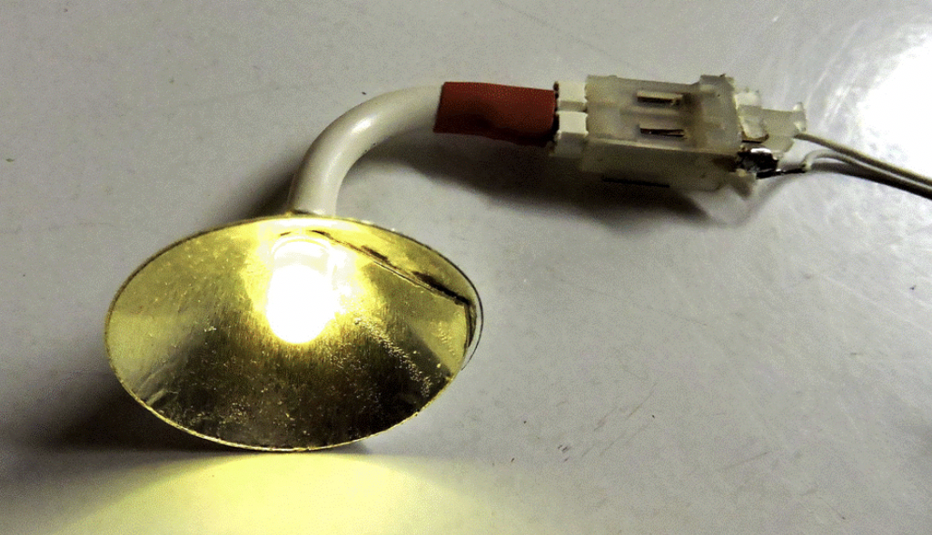 |
| Figure 1. Tram Station External Light Fixture |
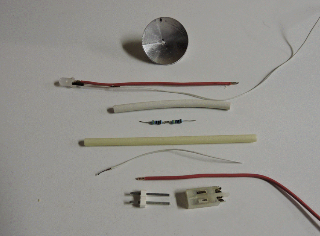
Figure 2 shows the assembled fixture at the top and the parts needed to make it below it. The shade was a 1 ½- inch circle cut from a scrap piece of clear plastic packaging material. This was soft enough to be bent into the conical shape, but also stiff enough the hold that shape. A wedge was cut out of the plastic disk and a dashed line marked to show the overlap which would produce the desired conical angle.
Unfortunately, we have found no glue that will adhere well to this clear plastic material. So, instead of glue, we used a circle of aluminum tape (the type normally used to seal heating and cooling ducts). This would hold the overlap in place, keep the shade in its conical shape, provide a reflective inner surface, and provide an opaque liner to prevent light leaks through the shade. The tape circle was attached to the outside of the plastic disk; a slit was cut in the tape to allow it to overlap as well; and the disk was bent, overlapping the edges of the missing pie-shaped segment of the plastic, into the conical shape and held in that shape by the overlapping tape.
The other parts for the fixture were the following: a stiff insulated copper wire (shown in red), needed to hold the supporting tube in its bent shape and to feed electricity to the positive connection on the LED; a short length of thin doll-house wire for the negative connection; a short piece of shrink tubing to cover the wire-to-LED connection; a piece of vinyl tubing for the fixture’s supporting “pipe;” an electrical plug; a piece of large shrink tubing to hide the transition from the vinyl tube to the plug; and a wired socket (shown at the right end of the fixture in Figure 1).
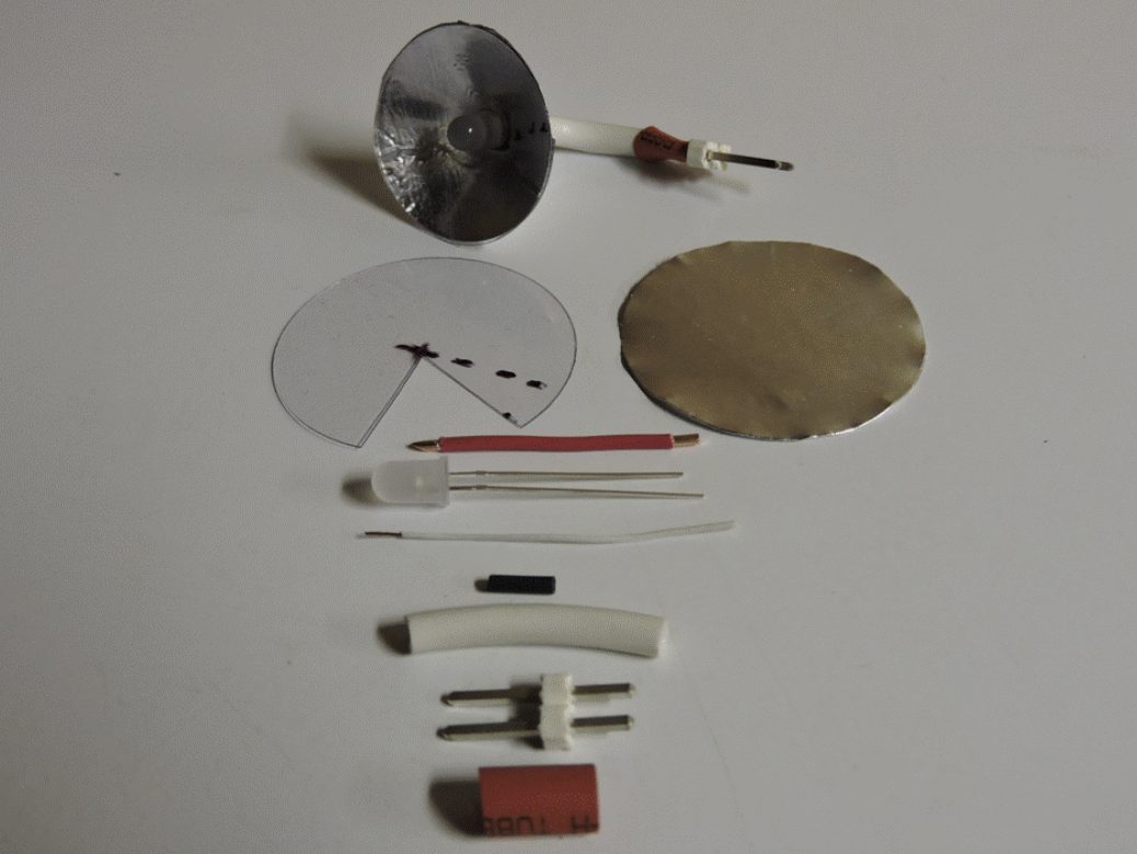 |
| Figure 2. Tram Station External Light Parts |
Assembly was fairly straightforward. The wire leads were soldered to the LED and the piece of shrink tubing was applied to the thin lead to prevent shorting from the aluminum tape on the fixture’s shade (Figure 3, top left). The wires were inserted through a hole in the center of the shade; the shade was moved up to the back of the LED; the wire leads were inserted through the vinyl tube; and the large piece of shrink tubing was placed over the vinyl tube out of the way (Figure 3, top right). The leads were then soldered to the plug (Figure 3, bottom left). The shrink tube was moved to the plug end and heated to shrink. The fixture was then plugged into a wired socket matching the plug and tested to make sure it worked (Figure 3, bottom right).
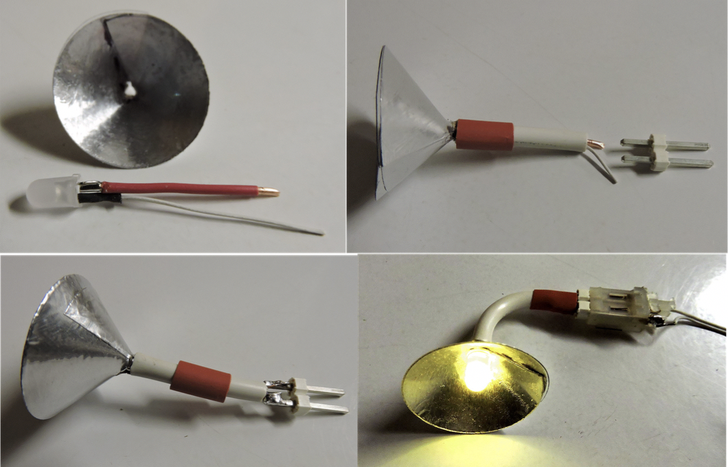 |
| Figure 3. Station Fixture Assembly Process |
Because there was no room in the lighting fixture tube for the resistors, they were included in one leg (usually positive) of the wire run leading to each socket. The sockets and their wiring were installed at the appropriate locations on the station buildings. Epoxy was used to hold the sockets in place. Epoxy’s gap-filling characteristic and compatibility with the various materials involved made it the glue of choice for this installation. Figure 4, left, shows the socket in place, and Figure 4, right, shows the lighting fixture installed, but as yet unpainted.
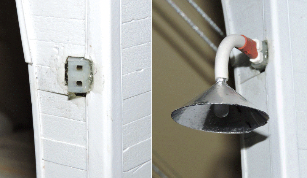 |
| Figure 4. Tram Station Light Fixture Mount and Mounted Light |
The stairway described in Report Number 146 also needed lighting, but these fixtures needed to be tall, self-supporting, and also removable. We chose to use the same LEDs, conical shades, plugs, and sockets. The upper support had a longer bent pipe at the top, and a stiff vertical pole to raise the fixture to a useful height. Figure 5 shows a completed fixture with its mounting socket. The sockets would be installed at the appropriate locations on the stairway’s retaining walls.
 |
| Figure 5. Tram Access Stairway Light Fixture |
Figure 6 shows the parts needed for the stairway lighting: the shade, the LED and wire leads, the vinyl tube, the resistor pair, a thin wire leader, additional stiff wire, the plug, and the socket. In this case the wire leads were left long for adjustment in length after installation of the vinyl tube. The short thin wire lead was temporarily soldered to the thick copper lead so that two thin leads could be pushed through the vinyl tube, and they could be used together to subsequently pull the thick-plus-thin wire assembly through the vinyl tube. (Because the fit of the thick-plus-thin wire assembly was fairly tight, pushing them through the tube did not work.)
 |
| Figure 6. Tram Stairway Light Fixture Parts |
Figure 7 shows the rest of the assembly process. At the top, the fixture with the added pull-through leader on the solid lead, is shown with the vinyl tube in place and the tube bent through the required 180 degrees. The solid wire extends farther out of the vinyl tube than in the building fixtures to make a stiff connection between the vinyl tube and the stiff vertical support tube. The middle view in Figure 7 shows the resistors installed, the addition of the lower solid wire section (for stiffening the connection to the plug), and the pull-through lead attached to the end of the lower solid wire. The thin wires are then fed through the solid tube and pulled through until the solid tube meets the vinyl tube. The pull-through lead is then removed; the large shrink tube section is installed out of the way; the solid and thin leads are soldered to the plug; and the shrink tube is put in place and heated to cover the plug joint (Figure 7, bottom). Then all that’s needed is to wire the socket and install it and its wiring on the stairway walls.
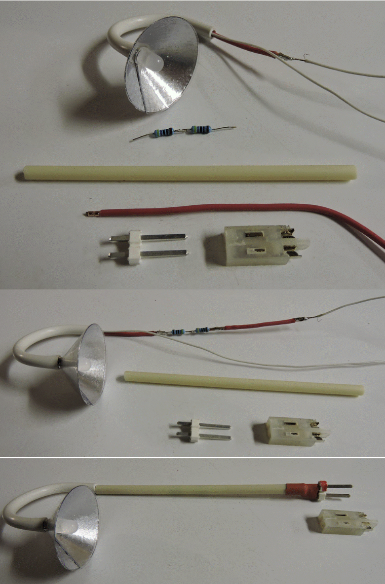 |
| Figure 7. Tram Stairway Light Fixture Assembly Process |
I have provided this rather detailed description of the lighting fixture assembly for several reasons. First, it documents what was done in case future maintenance is required on these lights or new ones, matching the old ones, need to be made to add additional lighting or to provide replacements in case of damage. Second it provides readers with ideas for making such lights for their own models. Finally, it illustrates again how, with just a bit of creativity, random non-hobby materials (like the aluminum tape, and the plugs and sockets) and even junk materials (like the clear plastic packaging and the tubing) can be used successfully to meet the needs of our scale modeling projects.
© 2019 Tom Bartsch
MVGRS Big Train Project Coordinator