
 Tickets
 Parties
 Shop
Shop Directions
#146 September Status Report
September 24, 2019
This month’s report describes the work underway to prepare the site for installation of the Lower Aerial Tramway Station on the EnterTRAINment Junction (EJ) layout.
In preparing last month’s article, I realized that there was no reasonable way for pedestrians or trolley riders in the Middle City to get safely down to the Aerial Tramway’s lower station. The access road would not provide a safe route for pedestrians since it’s just wide enough for two cars traveling in opposite directions to pass each other, and there is not sufficient width to add a sidewalk. Also the extra distance and slope of the road would not make it a pleasant walk for tram and restaurant customers walking either up or down. Solving this problem requires the addition of a stairway between the Stockyard building and the upper entry to the access road adjacent to the trolley-stop-island on the upper level (Figure 1).
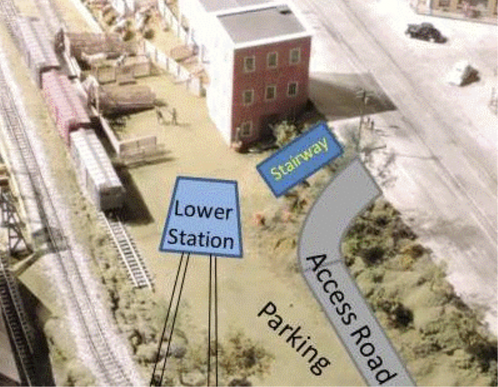 |
| Figure 1. Aerial Tramway Stairway Access |
The stairway needed a height of fifteen scale feet (7 ½ inches). Tread width was chosen to be 5 scale feet (2 ½ inches); tread depth was chosen to be 12 scale inches (1/2 inch); and the step height was 5.14 scale inches (determined by the thickness of available step material – a solid, but stiff low-density plastic that was the backing for some signs). The stairway required 35 steps to reach the 15 scale feet height. In order to fit the stairway in the available space, the stairs were divided into three reversing flights with a 2 ½-inch deep landing between flights. The upper two flights had ten steps each, the lowest flight had fifteen. Because there was no need for a landing at the bottom, the bottom flight could have five more steps than the other two and the last step would then be even with the stairway side-wall.
Having made model steps before, we knew making and supporting steps could be a tedious process unless we developed a way to make the steps quickly, accurately, and consistently to the needed sizes, both in width and in depth. So, to do this, a table saw was used to cut 2 ½-inch wide strips of the step material. These were then cut to length on a chop saw with a stop set for the lowest step in each flight (the longest in each stack, as seen in Figure 2). After each cut, a ½-inch spacer was added between the previous stop and the piece to be cut, to shorten it by the ½-inch tread depth. This technique allowed the steps to be cut in a matter of minutes.
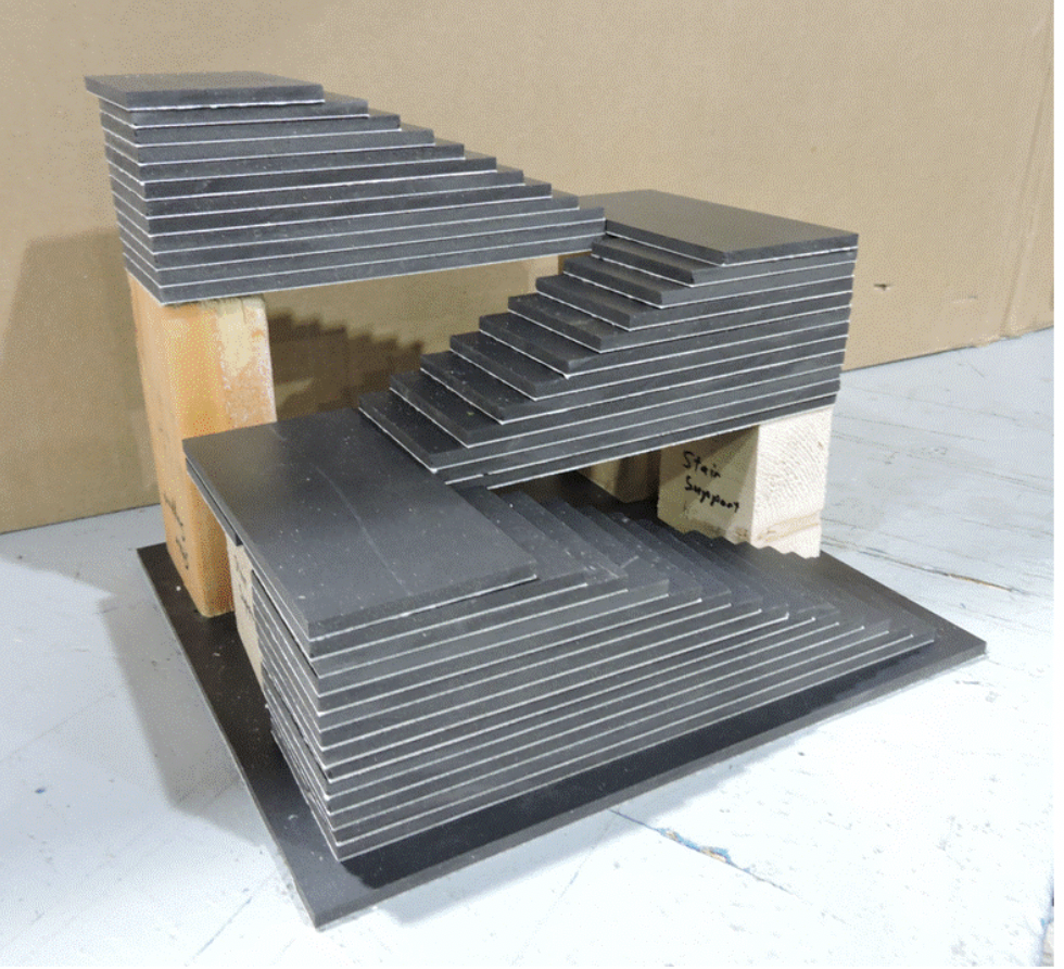 |
| Figure 2. Lower Tram Station Access Stairway Bare Assembly |
Retaining walls, using the same large-brick facing as the access road’s retaining wall, provided coverings for the sides of the flights and also provided railings, which were set to about 3 ½ scale feet above the walking surfaces. Figure 3 shows a trial assembly of most of the stair-related pieces. Missing are the caps on top of most of the wall sections. Also needed are lights, which will be mounted at the stairway entrance and at the bottoms of each of the sloped-top retaining walls. The design for these lights was still in work at the time of this writing.
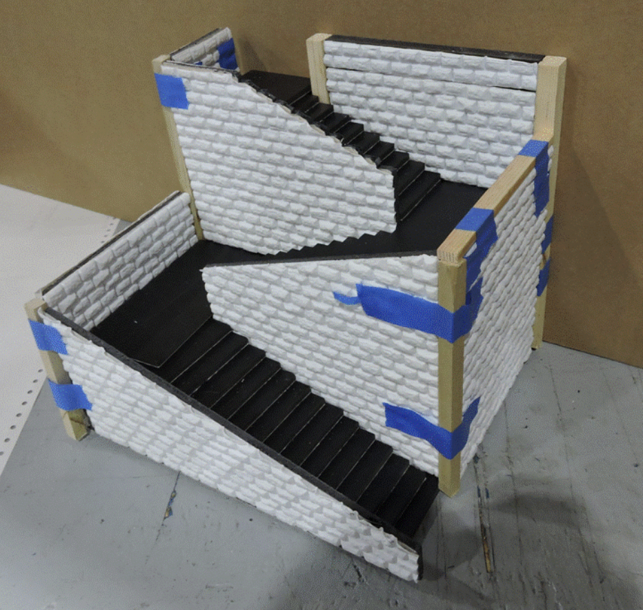 |
| Figure 3. Tram Access Stairway Trial Assembly |
Figure 4 shows another trial assembly of the access road with some of the completed retaining wall sections and some still under construction. To simplify installation, the road comes apart in two sections, and each of the retaining wall segments will stay separate until installed on the layout. The retaining wall sections have reference blocks on their backsides which are screwed onto the road, and there are reference blocks on the road supports to ensure proper positioning of each of the retaining wall panels. Given the lack of contrast between the color of the panels and that of the road, the road will need to be repainted a darker color (most likely simulating asphalt).
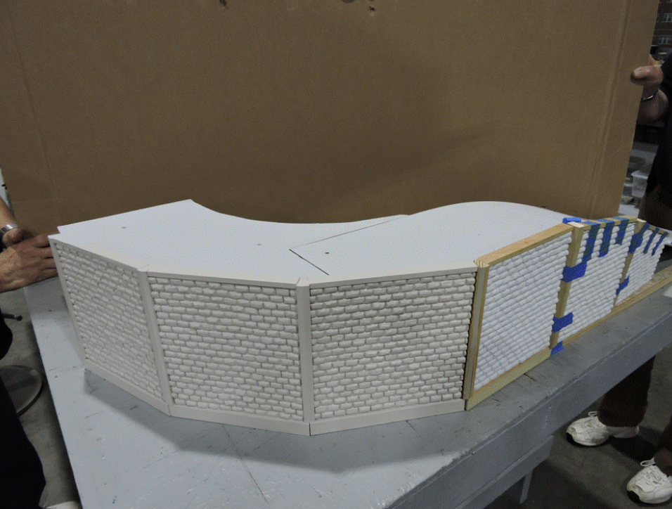 |
| Figure 4. Lower Tram Station Access Road and Retaining Wall |
As the work has progressed, a lot of additional details have come to mind which are needed to make the scene more realistic. And, while “better” may be the enemy of “good enough,” EnterTRAINment customers deserve to see models which are well thought out and complete in their representation of a realistic scene. So we try to build in all that’s needed up front, rather than add it later. And, as with the tram stations, getting the details of this installation right has taken more time than anticipated. Our objective remains to minimize disruption of the layout by making the installation process itself as quick and as simple as possible. Thank you for your patience… we’re getting there!
© 2019 Tom Bartsch
MVGRS Big Train Project Coordinator