
 Tickets
 Parties
 Shop
Shop Directions
#174 – October Status Report
October 27, 2022
Crossing Gate Repair
This month’s report details the work done to repair the crossing gates located at two road-track crossings in EnterTRAINment Junction’s (EJ’s) Modern City (one pair across from the restrooms and the other pair across from the entrance to the Display Area). The first pair of gates appeared on the layout in March of 2012 near the display area, and later the second pair by the restrooms in early 2018. In recent times, the gate arms have occasionally failed to stop their downward rotation and been broken by being forced into the layout surface. Our project task was to stop this from reoccurring.
The crossing gate actuation mechanism, hidden below the layout is beautifully elegant in its simplicity and in its effectiveness (Figure 1 left). The control boards (one of two shown in Figure 1 right) are much more complex, controlling not only the gate opening and closing, but also the flashing lights and the bell sound when the gate is in the process of “closing” the crossing. Further, a programmable logic controller mounted to each board determines when the gates need to be closed, based on input from magnetic sensors activated by the trains before and after the crossing on each of two or three sets of tracks. The trains on those multiple tracks are not synchronized as to when they go through the crossing and they do not run in the same direction, so sometimes more than one train can be in the crossing simultaneously. Rather complex logic is required to correctly keep the crossing gate down to deal with this fairly random situation, and a sophisticated computer program is required to make it work correctly and realistically. Another feature of the gate design is the need for the gate to take a few seconds to move from the open to the closed position and vice-versa just like real-world gates, which do not spring instantly up or down.
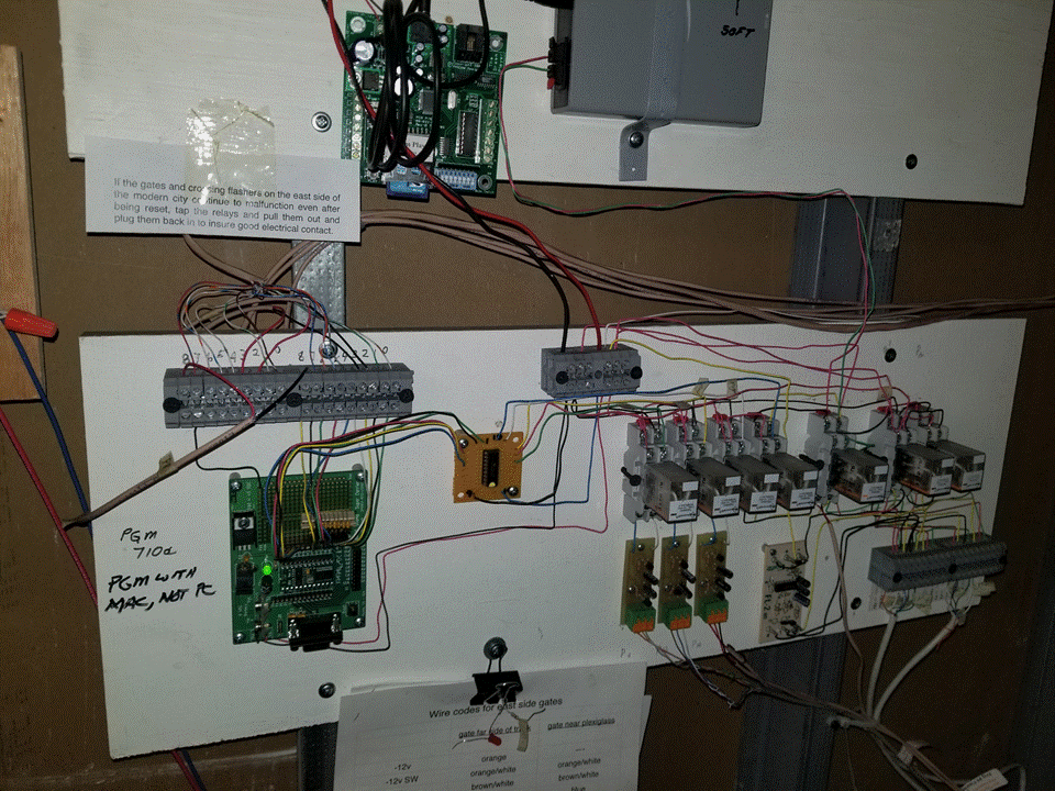
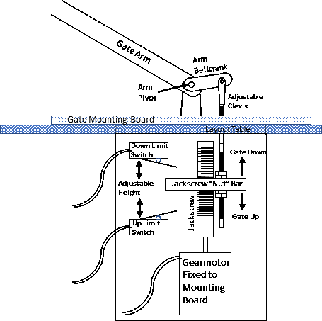
Figure 2 is a schematic of the gate actuation mechanism. In order to achieve the desired slow motion, a gearmotor is used to drives a jackscrew, with the linear movement of the jackscrew “nut” used to actuate the gate arm. The jackscrew “nut” is piece of solid steal bar with a threaded hole to accommodate the jackscrew. The bar is constrained from rotating as it moves up and down on the jackscrew by one side of the bar rubbing against a piece of plastic attached to the motor mounting structure. As the bar moves up and down, a pushrod attached to the bar rotates a bellcrank attached to the gate arm, which in turn rotates the gate arm up or down. When the bar actuates either the Up or the Down limit switch, the circuit to the motor is broken and current to the motor is shut off stopping, the motion. The very large mechanical advantage of the gearmotor-jackscrew combination provides enough force in the motion to break things rather than stalling the motor if limits are exceeded.
The circuit that is part of the gate mechanism is shown in the schematic in Figure 3. Note that there are three input wires from the gate control panel only two of which are used at a time.
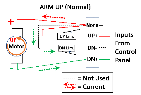
Without insight into the details of the circuitry and logic of the control panel, we do not know why this somewhat unusual three-wire arrangement was used (versus a more common two-wire reversing circuit). It turns out this three-wire circuit has a “sneak,” an undesirable function, which resulted in the reported failures when some failure mode in the control panel sent the wrong polarities to the wrong input wires.
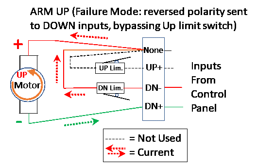
Figure 4 shows a comparison between the normal gate down current flow and the failure mode flow. Note that the failure mode uses the supposedly unused leg of the circuit, thereby bypassing the limit switch in the Down direction, and allowing the motor to keep running even after the down limit has been reached.
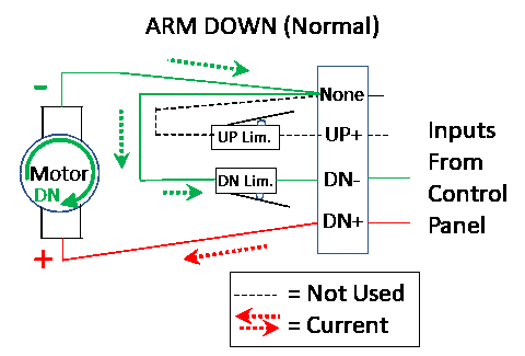
Figure 5 shows the equivalent situation for gate up motion. Here too, the supposedly unused leg of the circuit is used, bypassing the Up limit switch.
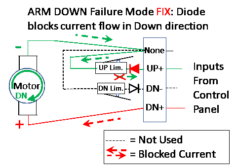
The solution for preventing gate movement when erroneous inputs come from the control panel is fortunately very simple: inserting a diode in each leg of the circuit going through the limit switches. Figure 6 shows the circuit diagrams with the diodes in the needed orientations between the input and the limit switches. With the orientations shown, the diodes allow current to flow in the correct direction and block current in the opposite direction. This does not fix the problem of an incorrect input, but it does prevent such an input from causing the mechanical system to damage itself with motion beyond the limits.
The problem of erroneous inputs will require further investigation, but its occurrence is no longer critical, since all that results is a gate that doesn’t move the way it’s supposed to. The basic construction and programming of the crossing gate control panels has yielded successful operation for many years, so continuing to use them would seem to be the logical approach. And, since the control panel uses replaceable relays whose failure modes are the most likely source of the erroneous inputs, it may be possible to prevent future erroneous inputs by simply replacing all of the relays involved with the motor operation.
A lesson learned from this crossing gate problem echoes the same lesson learned from the functional problem experienced by the incline, addressed in last month’s report: enforce operating limits with hard-wired circuitry, at least as a backup, rather than relying solely on the controller to enforce those limits. In both cases, proper use of limit switches and diodes were the keys to solving the problem.
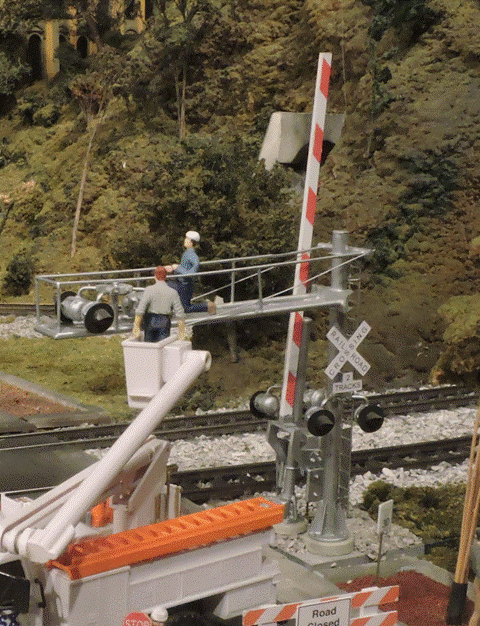
The next time you visit EJ, take a look at the visible parts of the crossing gates and their lights and see what a great job was done by our volunteer modeler, who built them and programmed them to look and to function like the real thing.
© 2022 Tom Bartsch
MVGRS Big Train Project Coordinator