
 Tickets
 Parties
 Shop
Shop Directions
#173 – August Status Report
August 4, 2022
This month’s report details the work done to repair the EnterTRAINment Junction’s (EJ’s) Inclined Railway and return it to operation.
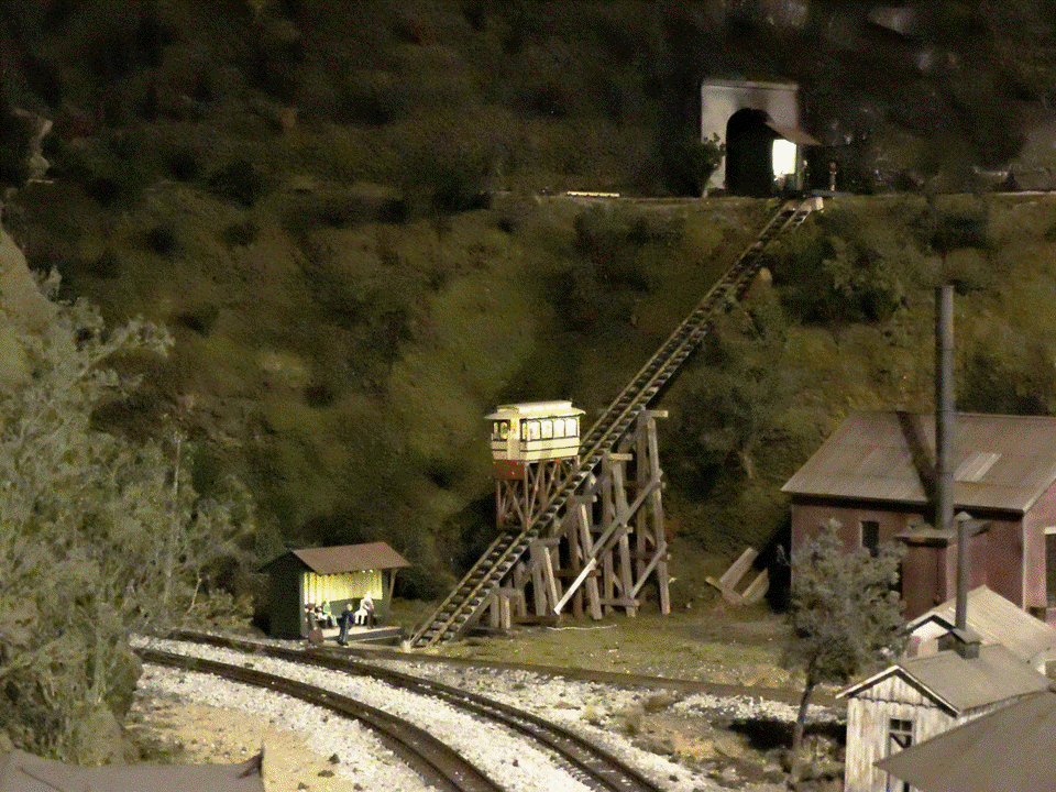
EJ’s Inclined Railway, or Incline for short, is located behind the Roundhouse in the EJ layout’s Middle Period (Figure 1). Its purpose is to provide passenger access between the lower level Engine Servicing Facility and the mid-level interurban railway, which runs along the hillside above the engine facility.
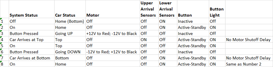
The Incline has been on the layout since November of 2013, but it wasn’t operational until January of 2014. The Incline car’s movement is actuated by a button on the EJ aisle, after which the car traverses the track in one direction. During the run, the button is disabled (with button’s light off) until the traverse is complete. A subsequent button push makes the car go back in the other direction. Figure 2 shows the operational sequence (easy for a computer program, but not so easy for an electromechanical control system).
Recently, the failure of the motor to stop when the car reached the top took the incline out of service until it was repaired.
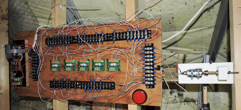
The original Incline control system is shown in Figure 3. The power supply is at the far left; the motor to drive the car via a “cable” (monofilament fishing line) is at the far right. The system also has a second “cable” which is attached to a counterweight connected to the car. This partially offsets the weight of the car and reduces the load on the drive motor. The five relays (electromagnetically driven switches) in the center of the board constituted an analog computer, whose hard-wired logic executed the operational sequence in Figure 2. A circuit diagram was available for this controller, but labelling of it and the board and its attached wires was very sparse, making it challenging to decipher which wires and which relays did what function. Troubleshooting the control on the bench confirmed that at least one of the relays had failed. It was unclear whether replacing just that relay would fix the problem, even if a replacement could be found.
The conversion of EJ’s main controls to using a digital computer system subsequent to the Incline’s creation provided a more available and simplifying option for the Incline repair than fixing the old controller. The same design of circuitry and control software used for EJ’s Aerial Tram could be easily adapted for use for the Incline. The “hardware” side of that adaptation is shown in Figure 4, with its simple motor limiter circuit in the center and its over-the-top-obvious labeling for all the necessary connections to and from the layout and to and from the computer. The wires connecting it to the layout and to the computer are not shown. The original Incline’s motor, pulleys, counterweight, and cables could still be used after the repair.
The labelling is intended to address the key problem experienced while troubleshooting the original controller: the individuals involved with its design and construction were no longer available for assistance. Similarly, some of us who worked on this repair might not be available in the future, hence this article documenting what was done and the heavy labelling on the board. The size of the mounting board was chosen to span the 16-inch-spaced 2×4 studs to which the old board was mounted. That left lots of room on the board for labels, and in large font. A feature we added to this control board was an option to drive the movement of the Incline car, via a selectable three-position toggle switch, independent of the computer which would normally drive it. Note that most of the inputs are labelled “polarity indifferent.” That’s because the inputs are from on/off switches that don’t care which direction the current flows through them. The only connections that are not indifferent are the sequence of black-and-red-wired motor inputs which, obviously, would change the direction of motor rotation, and hence the car’s movement, when the polarity is reversed. Wire-pair colors were specifically chosen to be different for each of the separate functional connections with the layout to make their function easier to identify when disconnected from the board.
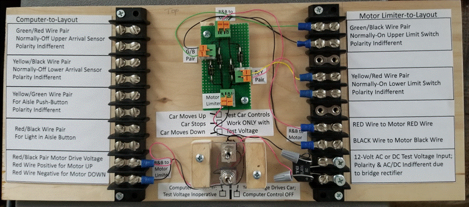
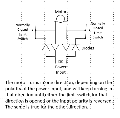
Figure 5 is a circuit diagram of the motor limiter circuit, which is used to stop the car’s movement at the ends of its travel in either direction, regardless of what the computer tells it to do. This is the same circuit used on the Aerial Tram and on the Ball Signal, both described in previous editions of this report. Use of this circuit provides a, hopefully, more reliable backup to prevent recurrence of the failure mode that drove the need for this repair.
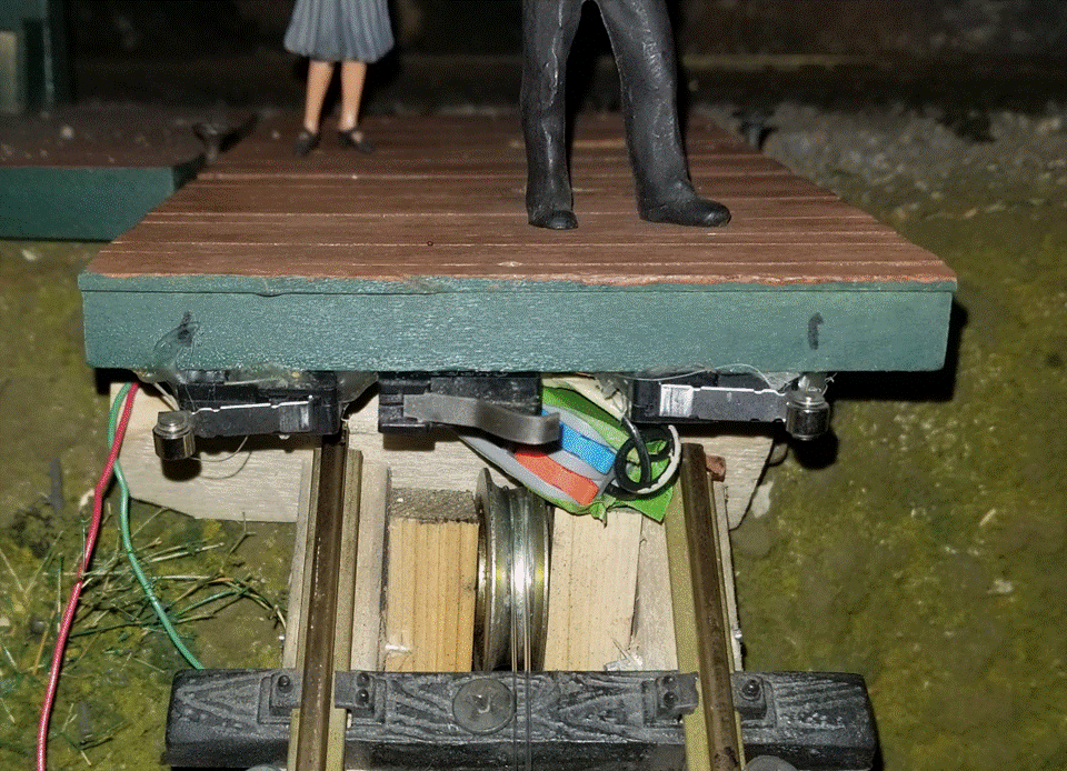
The normally-closed limit-switches and their wiring were the only new electro-mechanical components added as a part of the Incline repair. These switches are at the center of the sets of three microswitches that are attached to the bottoms of the platforms for the Upper Station (left) and Lower Station (right) shown in Figure 6. The gray quick-connectors with the blue and orange levers are GKEEMARS brand Mini Wire Connectors that allow easier removal and replacement of the screwed-on limit switches without the need to cut their wiring at the micro-switch ends. The two arrival-sensors to either side of the central limit-switch are glued to the station platforms and have soldered wire connections, making their replacement a much more difficult and potentially more damaging activity. Fortunately, they still work as needed. The arrival sensors are pairs of normally-open switches wired in parallel at each station (meaning that actuation of either or both of the two will send the completed-circuit signal to the computer). Because of this redundancy, both have to fail for the system to generate a failure error.
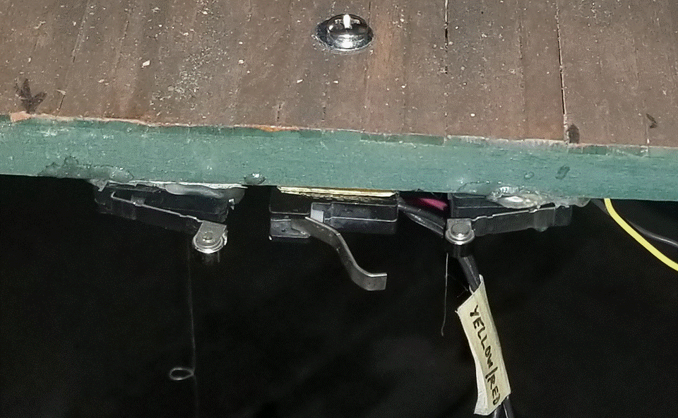
A critical adjustment of the relative positions of the two types of sensors is that the central limit-switch must NOT shut off the motor before the car actuates at least one, but preferably both, of the arrival-sensors located on either side of the limit-switch. If the car is stopped but neither arrival sensor is actuated, the computer will not know that the car has arrived and so generate a failure error when its transit-time timer runs out. Fine adjustment of the limit switch was available by bending its lever. The critical point is not where the car touches the lever, but where the lever has moved enough to actuate (turns off) the switch. Figure 7 shows the limit-switch on the lower station platform with its lever bent fairly far out to achieve the necessary actuation. On the lower station platform, which is glued solidly to the layout and not removable, a courser adjustment is available. That limit-switch is attached to a block of wood which in turn is attached to the bottom of the platform with the screw shown at the top of the figure. Enough room is left under the platform to allow the block to be moved about ¼-inch to or from the edge of the platform by lengthening the hole for the attaching screw and then reattaching the screw in the new location.
Most electrical and mechanical systems have failure modes which will eventually rear their ugly heads, especially in systems that get a lot of use over time. Inevitably, such systems will need repairs. And repair options are usually limited by the ability to determine what has failed, by the available access to the failed item, by the availability of repair parts, and by a potentially wide variety of other subtleties. The satisfaction gained from doing a repair comes from solving the puzzle of finding the failure cause and then devising and implementing an achievable solution with few if any downsides. But then, when undertaking the repair, it also becomes useful, if possible, to including some maintainability features (like better accessibility, better labelling and documentation, added test capabilities, etc.) which might make it easier for the next person who has to repair the system in the future.
© 2022 Tom Bartsch
MVGRS Big Train Project Coordinator