
 Tickets
 Parties
 Shop
Shop Directions
#171 March Status Report
February 28, 2022
This month’s report is about the rework of the ball signal that operated at the turntable end of the town of Riverbend in the EnterTRAINment Junction (EJ) layout’s Early Period. It’s another example of how the EJ modelers use electro-mechanical design concepts to create operating models for the layout. Also, this report provides documentation of what was done to help with later maintenance or rework of the signal, should it be required.
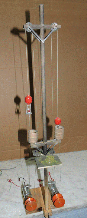
| Ball signals were used in early railroading to tell the train engineer whether or not the train was allowed to proceed onto the track section ahead. A “high ball” meant it was clear to proceed. A low ball meant “stop.” In the Early Period of railroading, such signals were manually lit and raised and lowered manually by railroad employees. Figure 1 shows the signal, as received for rework. The model included balls for two tracks (left and right relative to the signal). The modeled signal also includes modeled lanterns (not light-able) and barrels meant to hide the lights when the ball was lowered (no visible light at night meant no high-ball). The signal was positioned next to where the single track mainline at the town of Riverbend splits into two to allow trains operating in opposite directions to pass each other. Simulating manual operation, the model was driven by direct-current (DC) electric gearmotors mounted below the layout, allowing each signal to be operated mechanically independently of the other. The control mechanism was not provided with the model, but was assumed to be no longer functional, which was at least one of the reasons for the needed rework. Unlike in Figure 1, the model was supported on the layout by the flat plate seen just below the barrels, with the motor support hanging below attached to the signal support pole. Tension on the “ropes” was applied by stetting the motor support at an appropriate height. That method of tensioning required that both ropes be very close to the same length, because there was not much “springiness” in the system to make up for mismatches. Another issue that we did not discover until after the rework was almost complete, was that the bolts that were intended to fasten one of the pulleys to the motor shaft were not actually long enough to make contact with the shaft when tightened all the way, leaving the pulley to be held in place only by friction. The bolts were replaced with longer ones. | |
Experience with EJ’s Aerial Tram taught us that controlling the tensioning of “ropes” meant to drive objects on the layout was an important part of their successful use over time. With that in mind, it was determined that the easiest way to provide tension to the ball signal ropes was to use the weight of the drive motors. However, the positions of the motors, even though allowed to move vertically for tensioning, needed to be carefully controlled horizontally so that the horizontal positions of the ropes would not change significantly. This was to ensure proper interface of the rope with the limit switches that told the system where to stop the movement of the signals. To use the motors this way, we mounted them on the ends of two parallel beams hinged at the end opposite the motor. Each motor and pulley unit would overlap the hinge-end of the beam for the other motor and pulley unit. To help us visualize how this would work mechanically, a Lego® mockup was built to make sure that this concept would work and to determine what king of shimming was needed to prevent interferences in the movement. Figure 2-left shows that mockup, looking at the pulley ends of the motors which are represented by the two-beam sections at the top of the mockup. Figure 2-right shows the reworked version of the motor mount from a similar point of view.
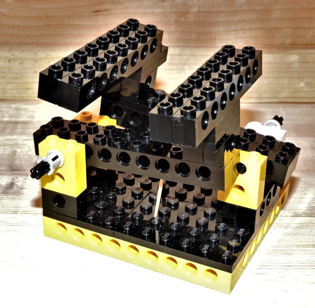
Figure 2. Motor Support Mockup and Reworked Mount
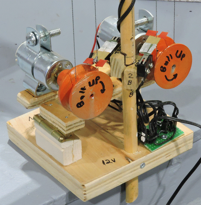
Figure 3 provides a view of the motor mount from the top, showing the two beams, labeled “1” and “2.” It also shows the hinge on beam “1” at the bottom center of the image below motor number “2.” To ensure that no one could miss that this is a twelve-volt system, it was marked as such in multiple locations.
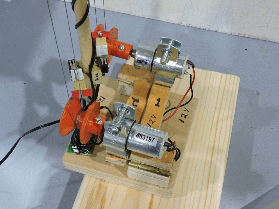
A critical change in this rework is the use of limit switches to stop the drive motors when each ball reaches either its minimum height (i.e., with the lantern in the barrel) or its maximum height. The switches used had three contacts: a common, one for circuit normally open, and one for circuit normally closed. For this application, we used the normally-closed, so that when the switch was actuated, it would break (open) the circuit, thereby stopping the motor. To get the actuation point of the switches where we needed then, we glued brass extensions to the switch levers (solder didn’t work because the switches’ levers were stainless steel). At the far end of each extension was a slot through whose center each signal’s rope would pass (Figures 3 & 4).
Attached to the rope was a bolt and nut assembly too big to pass through the slot. This would actuate the switches both at the top and at the bottom of the ball’s movement when bolt-and-nut contacted the extended lever (Figure 4). Given the direction of rotation marked on the motor pulleys, the switches shown are the stops for maximum height. The bolt is attached to the rope with one loop of rope wrapped around the bolt next to the head. The nut is used to hold that position when tightened. Fine adjustment of the stopping location is done by simply loosening the nut, rotating the bolt on the rope to the desired location, and then retightening the nut. For coarse adjustments, it would be easier to unwrap and rewrap the rope around the bolt at the new location. The critical adjustment point is to get the lantern in the barrel (low ball). The location of the high ball results when nut-and-bolt hit the limit switch at the farthest point down the pole that the structure will allow positioning of the lower limit switches.
While the setup is intended to have the rope not touch the edges of the lever extension slot, there is enough “slop” in the system that this may not always be the case. For that reason, we added plastic tape coverings over the slot edges, so that if the ropes did contact the edges they would not be worn or torn by the brass edges (Figure 4). The rope lengths were set so that the rope could have one wrap around the motor pulley with the motor levers being approximately horizontal. The single loop provided sufficient friction on the pulleys to avoid slipping, given the low resistance of the rope to its needed movement.
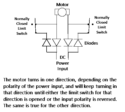
The control of each of the motors was via a simple circuit of diodes shown in Figure 5. The two circuits were installed on the same circuit board. The actuation of the signal is derived from the position of the track switch where the mainline splits into the two passing tracks. On the EJ layout, the position of operating track switches is controlled by the EJ computer system, which directs power to be continuously provided to the switch drive motor in the direction to keep the switch points where the system needs them to be. When the switch points are needed to move to the opposite position, the DC power polarity to the switch drive motor is reversed. By connecting the DC power input to the ball signal to the switch motor control power output, constant power is provided to each signal, which it uses to drive the signal until the power is switched off by one of its limit switches. The signal remains in that position until the power polarity is reversed, and the circuit bypasses the previous limit switch and rotates the motor until the other limit switch cuts the power. And so on.
The whole reworked ball signal assembly is shown in Figure 6. A new mounting plate below the barrels was added, large enough to cover the hole in the layout needed to lower the controlling parts of the signal down below the layout.
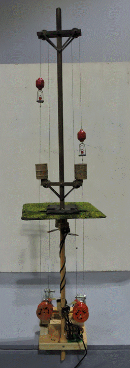
Figure 6. Full View of Reworked Ball Signal
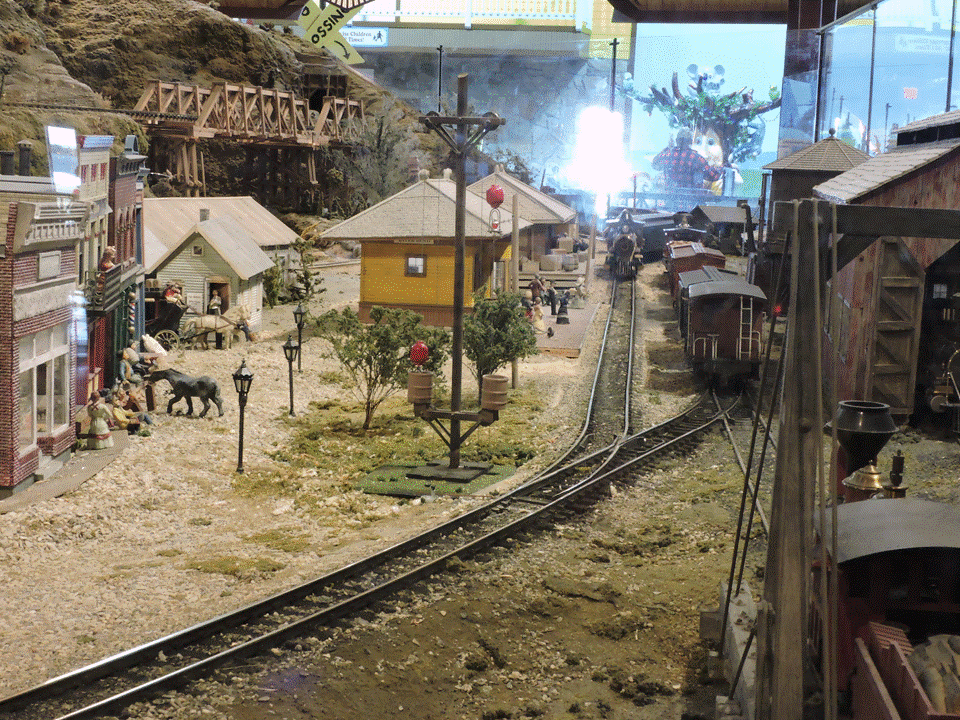
The reworked signal installed on the layout is shown next to the track switch that controls the signal’s positions (Figure 7). Note that the right track is authorized for entry (high ball), while the left track is not yet allowed to be exited (low ball).
For me, this was a very enjoyable project. It allowed the use of some creative engineering solutions to produce another functioning display item that also has relevance to showing how railroads operated in the past. If you’re a model railroader, you’ll know that operating two trains in opposite directions on a shared track is no simple matter. Controlling that action by programming the positions of the switches, the track section polarities, and the timing of it all was expertly handled for this location by the EJ crew. The operating ball signal takes advantage of that work and just adds another activity of interest to the action in the town of Riverbend. Come check it out on your next visit to EJ.
© 2022 Tom Bartsch
MVGRS Big Train Project Coordinator