
 Tickets
 Parties
 Shop
Shop Directions
#168 October Status Report
October 6, 2021
The Big Train Project Status Report (Part 168)
This month’s report is the second part of the story of the animated skaters for the EnterTRAINment Junction (EJ) layout. In last month’s report, I described the driving mechanism for the skaters: a turntable on a trolley. This month I’ll describe how we use that mechanism to drive the skaters in a somewhat realistic fashion. The objective is to move them along seemingly random paths using most of the available “ice” surface of the skating rink, and, more importantly, to have them facing their direction of movement.
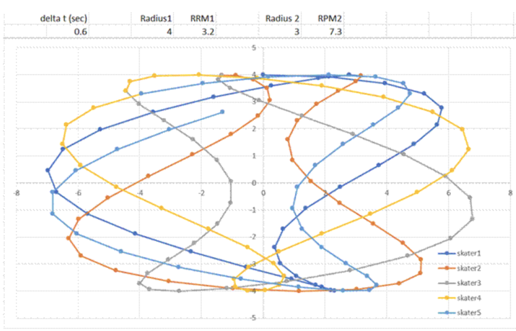
To visualize the kind of patterns of motion possible with the mechanism, I use the help of some mathematics (most usefully trigonometry) and the graphing capabilities of the Excel® spreadsheet software. Figure 1 shows one of the calculated results, beginning with the dark blue line (with the skater starting at x = zero and y = 4), and running for five rotations of the turntable. RPM1 is the turntable rotation speed, and RPM2 is the rotation speed of the trolley drive motor. The “magic” here is that the trolley cycles at a faster rate than the turntable AND the two RPMs are NOT even factors of each other (e.g., the trolley drive RPM is not exactly one, two, or three times that of the turntable). The RPMs shown successfully meet the first objective and are close to what is actually set on the real device.
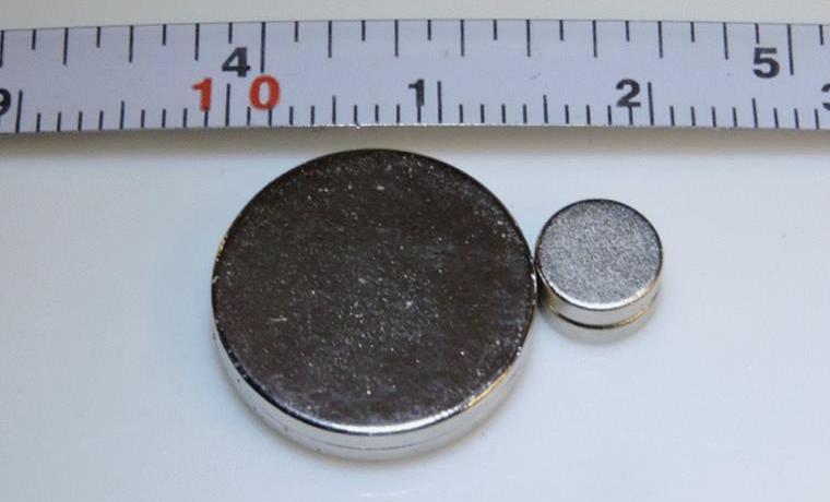
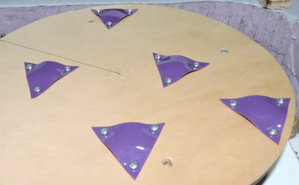
To move the figures of the skaters on top of the “ice,” magnets are attached to the turntable at somewhat random locations that spread the skaters out nicely. No skater is placed at the center of the turntable, because then its motion would just be a straight line, back and forth. Figure 2 shows the magnets used. The top scale is inches, the bottom is millimeters (mm). All are 2mm thick, with five stacks of two of 14mm diameter magnets mounted to the turntable, one 6mm magnet mounted to each skater’s “skate,” and one 6mm magnet mounted to each skater’s foot. Figure 3 shows the magnets mounted to the turntable using triangular plastic mountings held on by screws at their corners. A pair of magnets was used at each location to give extra pulling power and to ensure that, if there was contact between the bottom of the “ice” and a mounting, it would be on the slippery plastic and not on any of the screws. For interchangeability of skaters all magnets need to be oriented with the same polarity upward. That is easy to check by placing another magnet on top of the previously attached one. The loose magnet will flip to the correct side if it isn’t the same. Once correct, the loose one can be attached in that orientation at the next location.
The second objective, that of forcing the skater to face forward along its path of motion, required the creation of some special “skates.” Because the flat magnets’ poles are on their vertical axis, their rotational position on that axis does not generate any turning moments around that axis. To generate the needed rotation of the skater to face forward, the “skate” needs to do that by acting like a rudder. The only force that’s useful for that is the friction of the bottom of the “skate” with the “ice.” If the friction is highest toward the skater’s back, the skater will turn his or her back that way. Since the attractive force between the magnets increases the closer the magnets are to each other, placing the skaters’ magnets at an angle, downward toward the rear of the skater, places extra force to the rear. By elongating the skate behind the axis of the magnetic field, the back of the skate ads lever arm to the added friction force which then is enough to rotate the skater in the desired direction.
What was needed for the “skates” was some slippery plastic. That was provided by the remains of an old plastic (nylon?) cutting board. Cut into strips, the plastic was drilled perpendicular to its upper surface with 5/16 inch drill bit. The skate is then cut from the piece of cutting board as shown by the dashed line in Figure 3. The drilled hole is a tight fit for the 6mm skate’s magnet, which is pushed to the bottom of the hole after its polarity is checked against the turntable magnets. The magnet attached to the skater (also after a polarity check) then attracts and holds the skater to the skate, and the whole assembly is attracted (through the plastic “ice” surface) to the turntable magnets. The magnetic force holds the skater upright, even though it might not be balanced enough to stand upright if there were no magnetic force from below the “ice.” The magnets on the turntable drag the skater’s along the magnets’ paths.
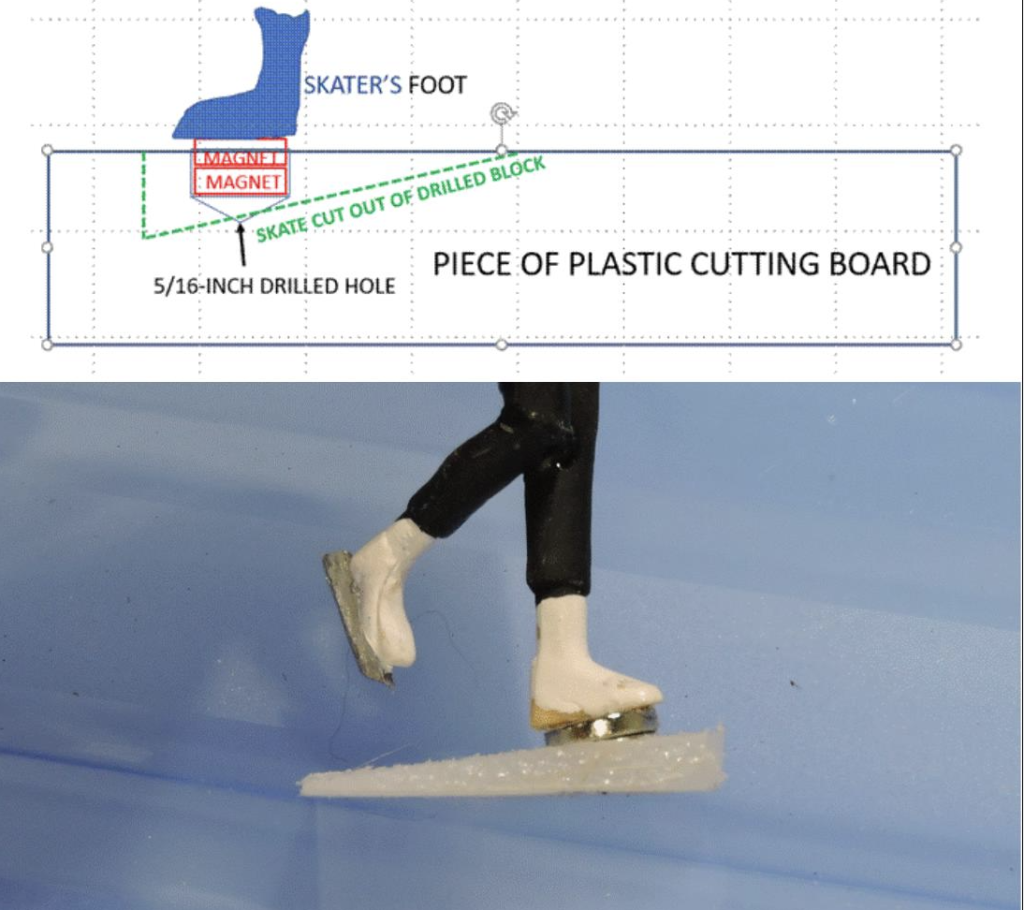
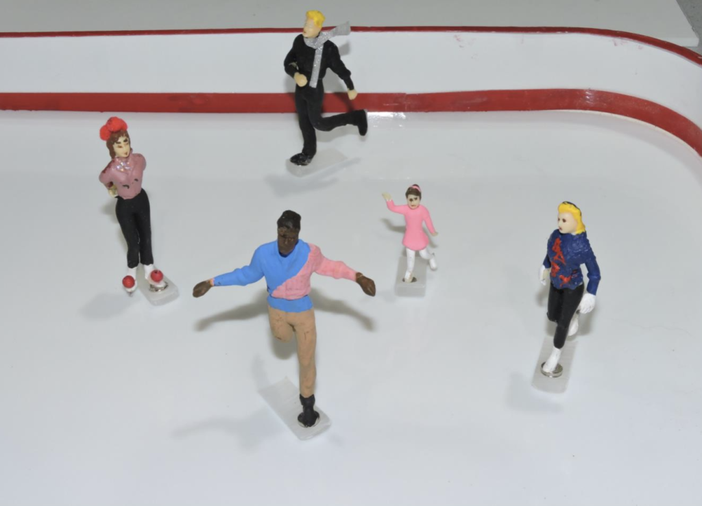
Figure 4 shows the set of skaters made for the five magnet sets on the turntable. The number five seemed reasonable so that the rink would not look too crowded, and there would be adequate spacing between skaters. Note that some of the skates do not align exactly with the skaters’ front-to-back line. When they are tested on the “ice” with the magnets moving, they are adjusted so that their movement is correct regardless of the resulting skate angle. The sixth skater (spare) has to have his skate turned almost backward to make his body move forward correctly (one of the vagaries and unpredictabilities of friction at work). Because the color of the skates is not that much different from the “ice” and the view of the rink from EJ’s aisle will be at a very flat angle, such “oddities” will not be very noticeable.
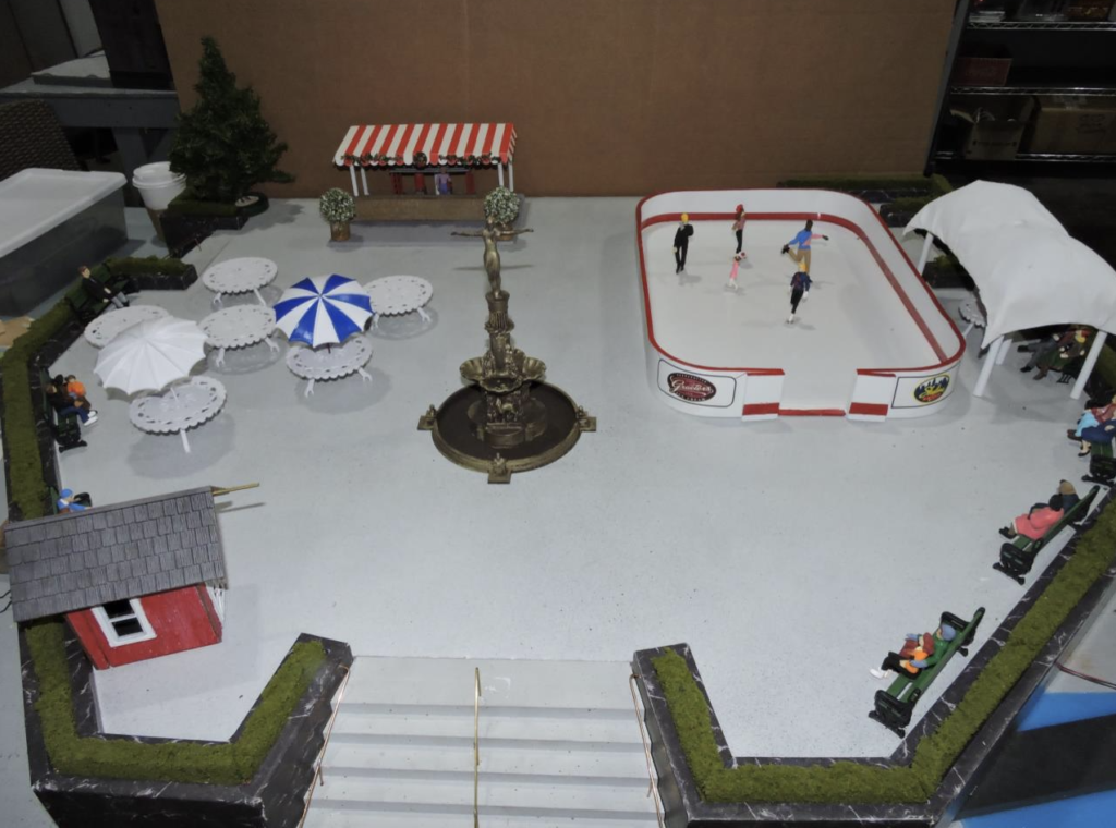
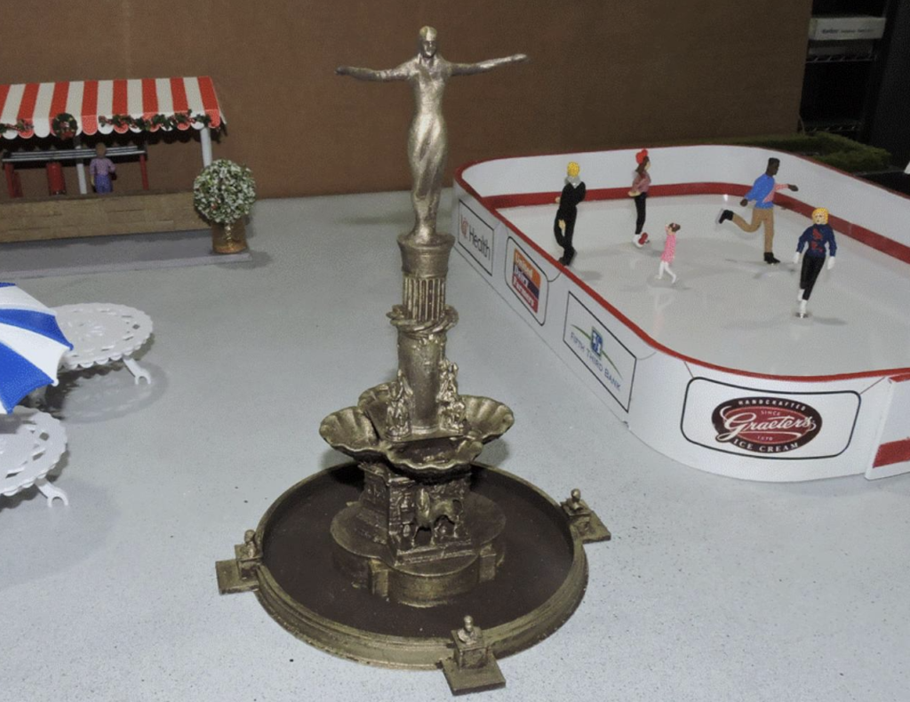
The almost completed town square will look much like Figure 5. It has not only the skating rink, but also a refreshment stand, benches, tables (eventually with chairs), and a computer 3D-printed replica of Cincinnati’s iconic downtown fountain (Figure 6).
With the addition of some Christmas trees and other décor items, this display will be ready to take its place on the EJ layout from November to January. So, if you want to come and be mesmerized by the motion of the skaters or just enjoy EJ’s Christmas décor and Christmas displays, be sure to come visit. You’ll be impressed by it all.
© October 2021 Tom Bartsch
MVGRS Big Train Project Coordinator