#157 September Status Report
September 15, 2020
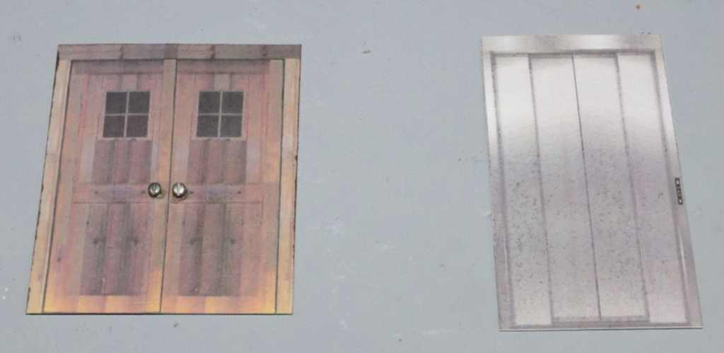
As mentioned is last month’s report (Part 156), We needed to simulate an elevator in the EnterTRAINment Junction (EJ) upper Aerial Tramway Station. Figure 1 shows the two related doors which would be “visible” on the model.
The door on the left is the ground-level access door leading to the elevator waiting area inside the station extension. This door is made in the same style (i.e., from the same photograph) as that was used for the platform-level door at the back of the station.
\We chose to make it 6-foot wide double door for customer convenience. The elevator door, shown at the right of Figure 1, was chosen based on the width of the station’s central 2×4-inch track-wire support column, which would simulate the elevator shaft structure. Since 2x4s are actually only 3½ inches wide (7 scale feet), this doorway had to be narrower (4 scale feet wide) to allow room for the elevator doors to open out of the way into the shaft structure to either side of the door opening and still leave room for the structure within the 7-foot width.
Also, this door used a double-door set on each side to reduce the width needed to “store” the door when it was open. These, of course, were only architectural design considerations, since the model door doesn’t actually open. It’s just a picture. But our attempts at trying to be realistic make us cautious that we don’t model something that would be an impossibility in the real world.
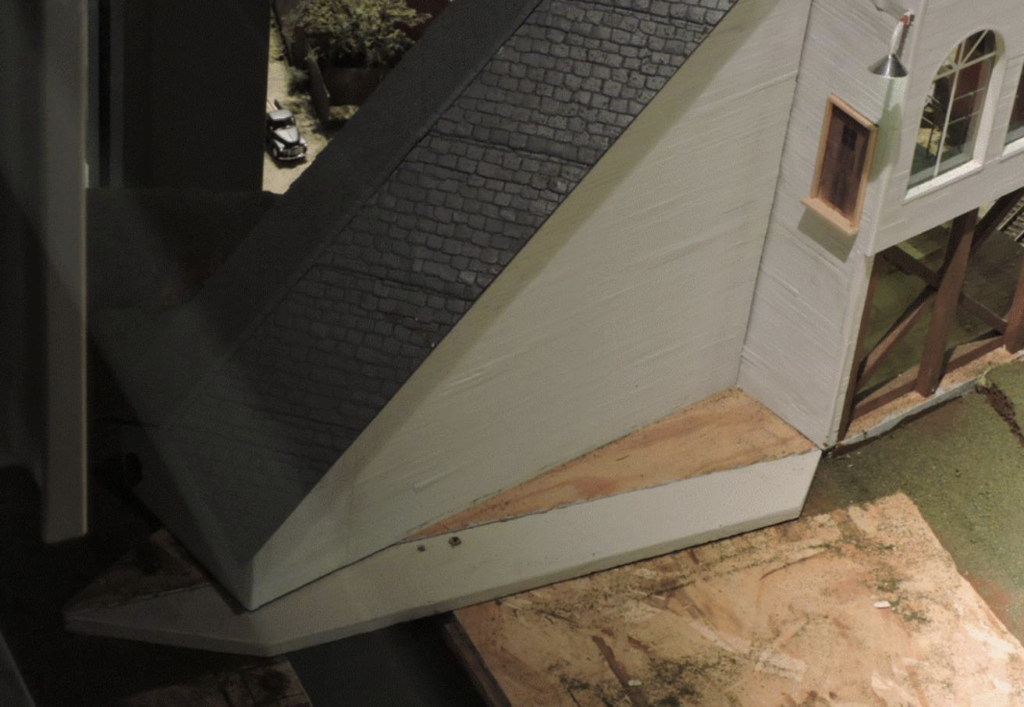
One of the other station features that needed modification was the station base. Since the stairway would end two inches away from the sloped station extension wall, well beyond the edge of the angled base, the base needed to be extend to accommodate the width of the stairway at its bottom. This would also protect the stairway from any installations of scenery adjacent to the station. Figure 2 shows the gray base extension. It’s also seen in Figure 5. The previous lack of paint on the wood-colored upper surface of the original base also looks like it needs to be addressed.
The extreme telephoto closeup in Figure 3 shows the elevator door installed at station platform level behind the waiting red-coated tram customer.
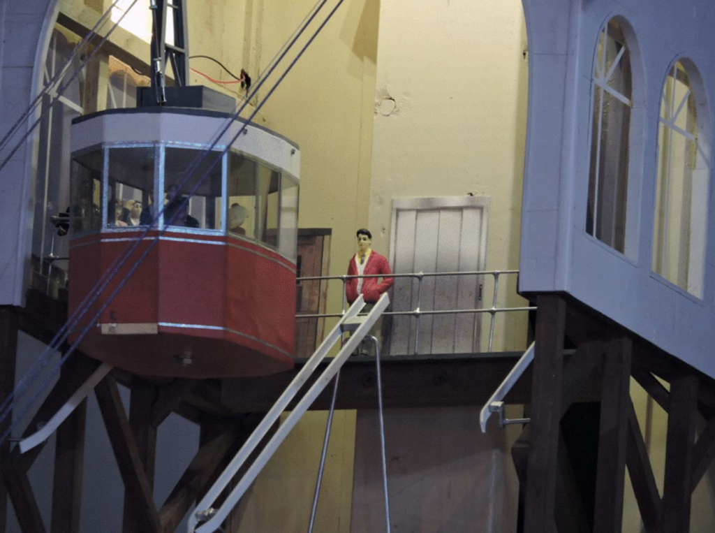
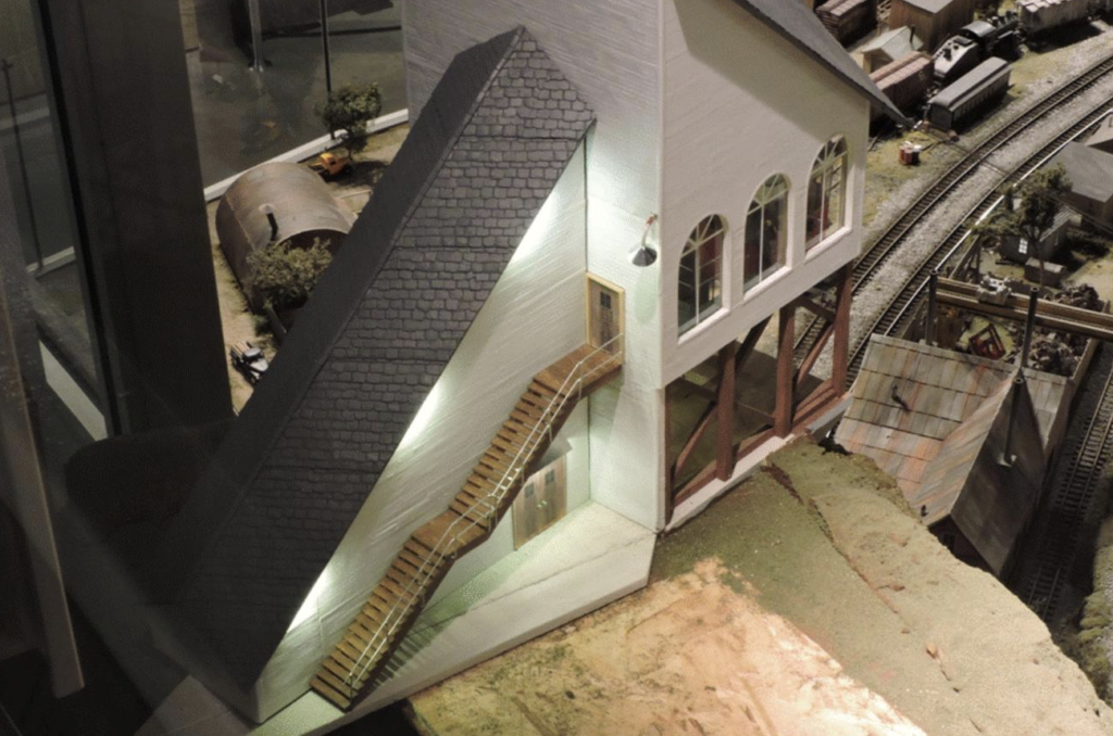
Figure 4 shows the stairway with its railing and the access door with its above-door lighting fixture all installed on the station extension. Just barely visible under the roof overhang above the bottom of the stairs and above the middle landing are 3-LED light sets for lighting this emergency exit stairway. Power for the lights is transferred from the main station light contacts (described in report Part 153) to similar contacts mounted just inside the lower right corners of the extension walls. This allows removal and (careful) re-installation of the extension without having to unplug and replug wire connectors.
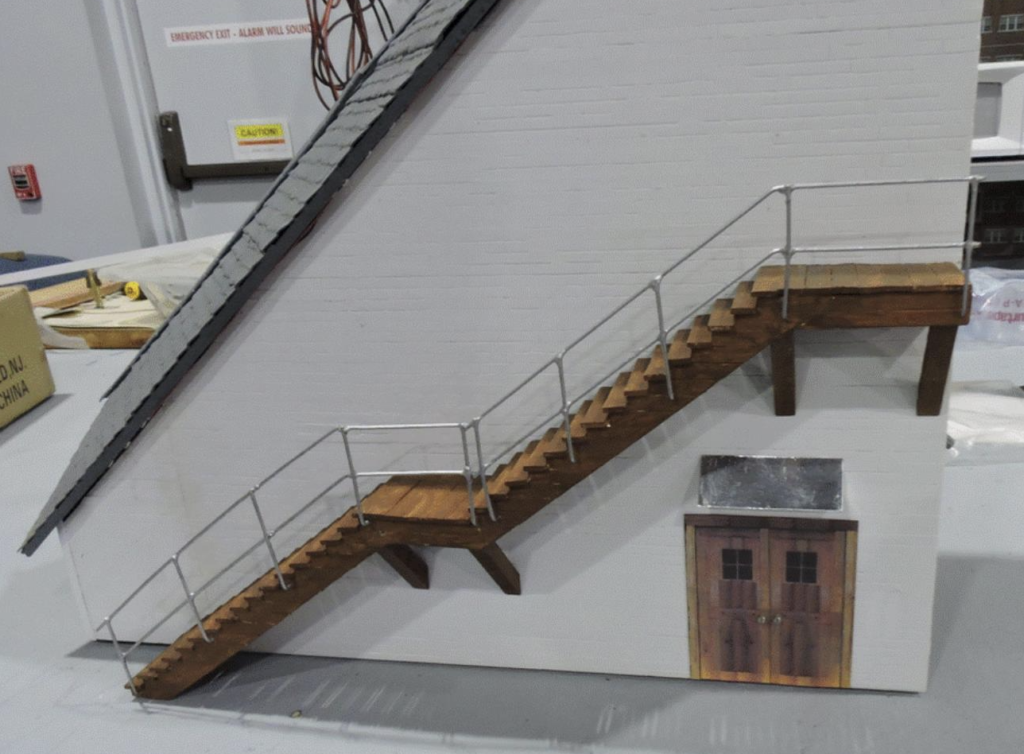
Figure 5 shows the station extension installed with all the lights on. The stairway ends right at the edge of the station base extension. Note that the portions of the station base that had previously been unpainted are now the appropriate concrete color.
With the station modification complete, the next steps will be finishing the scenery between the station and the restaurant. A key portion of that will be a lit and path at or near the cliff edge leading to the restaurant. Other features may include modular removable elements which will allow 1:1 scale workers to stand or kneel on the shelf to do maintenance on the works in the upper station without doing damage to the scenery. Another element may be some form of back-drop along the mezzanine wall. The first steps will likely be something temporary to be replaced when the more scenic scenery is ready.
Stay tuned, as the continuing evolution of the EJ layout proceeds.
© 2020 Tom Bartsch
MVGRS Big Train Project Coordinator

 Tickets
 Parties
 Shop
Shop Directions