
 Tickets
 Parties
 Shop
Shop Directions
#134 August Status Report
August 11, 2018
This month’s report is the fourth status report on the development and construction of EnterTRAINment Junction’s (EJ’) aerial tramway. The test fixture has been modified by raising the bottom of the lower station’s base plate to the height of the bottom of the layout table on which the station will ultimately be located. This enables any under-table structure and mechanisms to be built, fitted, and tested prior to their installation under the layout. Figure 1 shows the risers between the station base plate and the test fixture table. The two pair of vertical slats in the foreground hold the fulcrums for the track-cable tensioning levers. Under the layout, this structure will be attached to the layout table at the top and EJ’s floor at the bottom. Each cable pair is hooked to the screw eye in the top of the lever near the fulcrum; the water-bottle-weights are hooked to the screw eyes on the bottom of the levers at the far end. This gives about a 4 to 1 mechanical advantage (i.e., each cable pair is tensioned to four times the weight of the bottle).
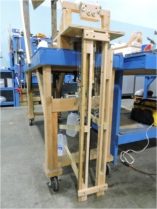 |
| Figure 1. Track Cable Tensioning System |
Figure 2 shows the levers and bottle-weights from the side. When actually installed, the bottles will contain sand rather than water (less mess if a bottle should break).
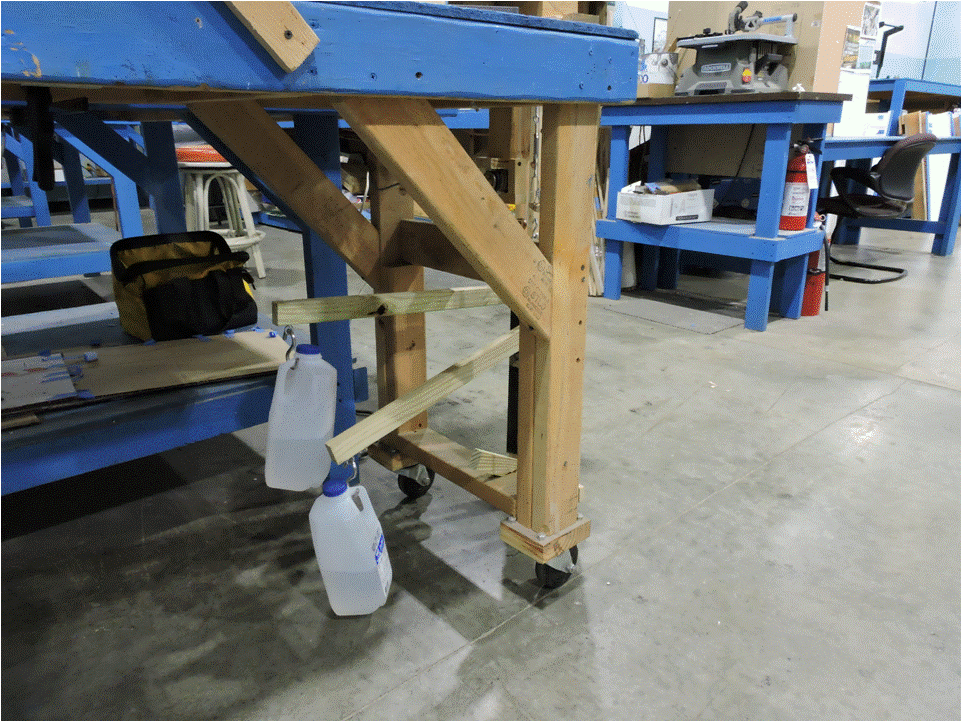 |
| Figure 2. Track Cable Tensioning Levers and Weights |
Figure 3 shows the connection of the right track cable pair to its tensioning lever screw eye. It also shows the haulage rope tensioner with its pulley and the suspended rectangular steel tube (lower center of the figure), which provides the weight needed to tension the haulage rope. Without a weight of this magnitude, the motor would turn, but there would not be enough friction between the rope and the motor pulley to move the rope, even with two turns of the rope around the motor pulley.
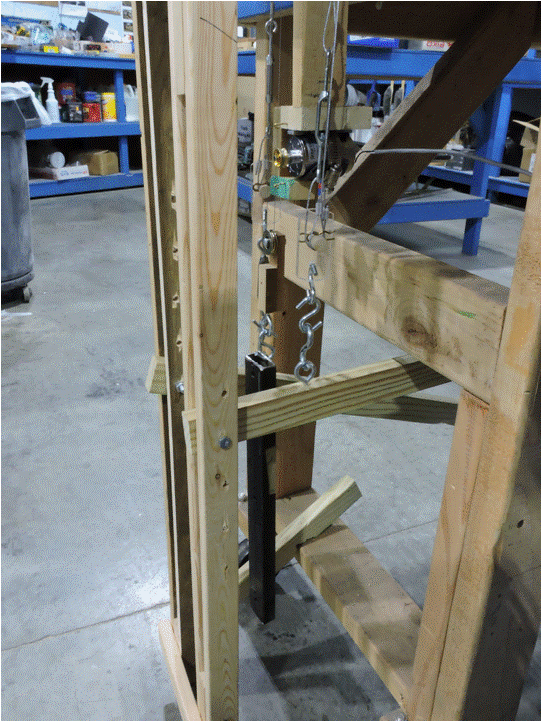 |
| Figure 3. Drive Motor Mounting and Haulage Rope Tensioner |
Figure 4 shows the track cable pair bracket (lower center foreground), which is a piece of thick clear plastic with a dowel going through it. The cables are looped around the dowel on opposite sides of the plastic, and clips keep the cable loops from slipping off. A turnbuckle on one cable of each pair is used to equalize the length of the cables in the pair, so that they have equal tension. The design and materials used in the bracket were chosen to simplify installation and removal of the cables and to electrically isolate the two cables from each other so that the cables can pass electricity to the tram cars lights.
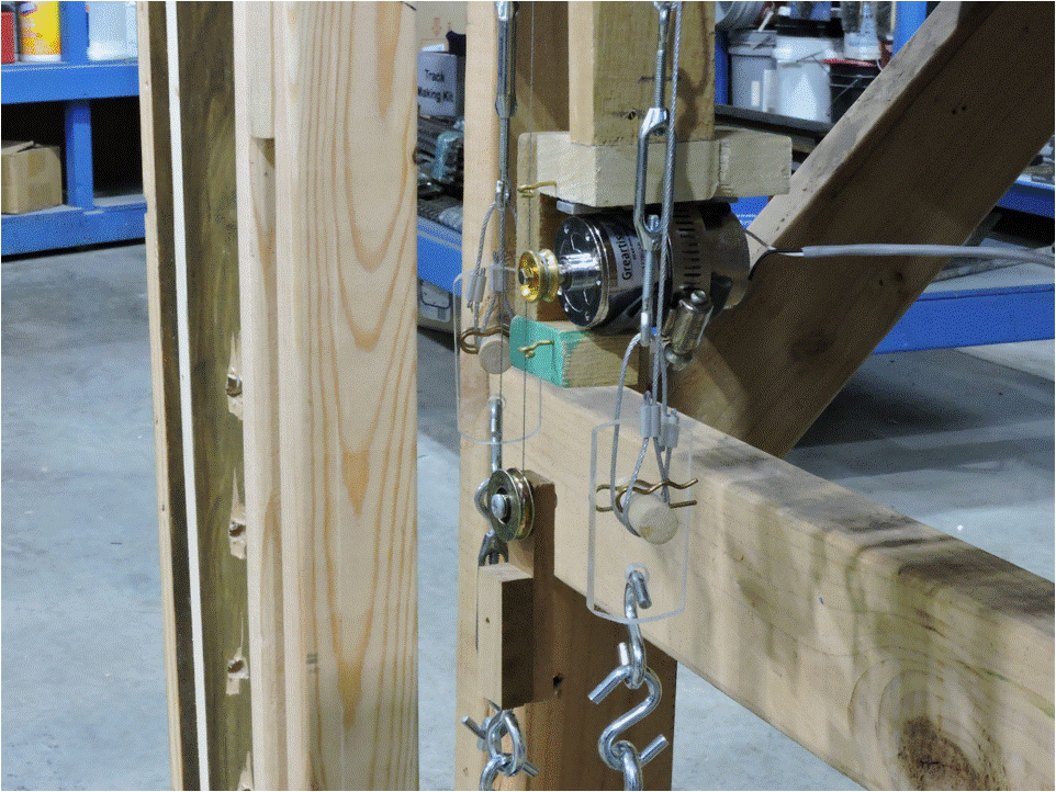 |
| Figure 4. Haulage Rope Drive Motor |
The motor mount is made of hefty pieces of 2”x4” wood to ensure an unmoving mount and to protect the motor from under-layout “accidents.” The mount has “pig-tail” guides above and below the motor pulley to restore haulage rope alignment with the motor pulley after maintenance or other disturbances. The guides are positioned in such a way that the rope does not touch them during normal operation. The pig-tail shape surrounds the rope but has an opening to allow installation of the rope into the loop without needing a loose end of the rope to thread the rope through the loop. The motor is positioned to the right outside of the right vertical haulage rope so that the rope remains vertical and is tangential to the motor pulley. The rope that comes from the right tram car takes two turns around the motor pulley, then runs down and around the pulley attached to the rope tensioning weight (the rectangular steel bar in Figure 3), and then runs back up eventually to attach to the left tram car. The motor is a twelve volt DC motor rated at 200 rpm. To run the tram cars at an appropriate scale speed requires only five volts, and the starting and stopping action is gentle and smooth enough that no electronic ramping of the speed is needed. That latter characteristic greatly simplifies the electronic controls needed to operate the system.
Figure 5 shows the four micro-switches which sense the tram car’s arrival in the station and stop it at the appropriate location. The switches have slotted mountings to allow adjustment of the stopping location. Each car drives two switches, a primary and a backup. Each switch has two modes: normally closed (allowing current to flow) and normally open (not allowing current to flow). Using rectifiers, the switches stop the tram car only in the down direction by opening the normally closed switch. The backup switch is wired in the same way in series with the primary. The normally open function from the primary switch is used to provide a zero resistance signal to the tram control system to turn off power to the system, to change its polarity (the direction of travel of the tram cars), and to await EJ customer reactivation from a button on the layout aisle’s wall.
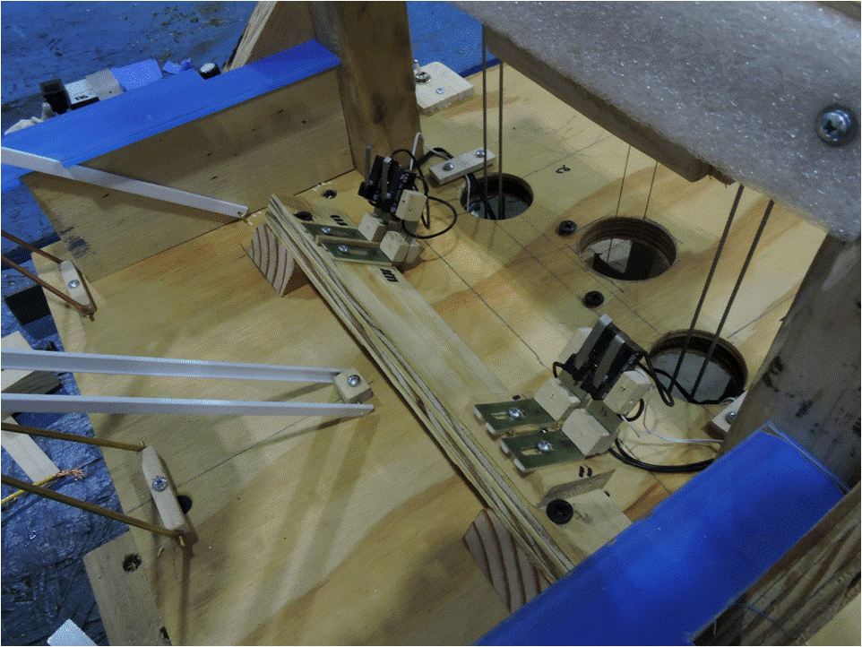 |
| Figure 5. Limit Switches |
The white foam pad in the upper right of Figure 5 is the last-ditch stop, intended to ease the tram car’s “landing” should the upper haulage rope break. The white narrow plastic channels at the left are sway guides which direct the tram cars into the station. They are found on real trams, and so are included in this model, though in the model they are more for show than for function, since the cars sway very little, if at all, during operation. The blue parts at top left and bottom right are the tops of the station’s loading platforms.
Figure 6 shows the cardboard mockup of the lower station used to check its fit, check clearances, measure angles, and act as patterns for making the actual station parts. The station walls and roof will be made of Gatorboard ®, which is light and strong enough to allow the whole building to be easily removed for maintenance of the tram components which the building normally covers.
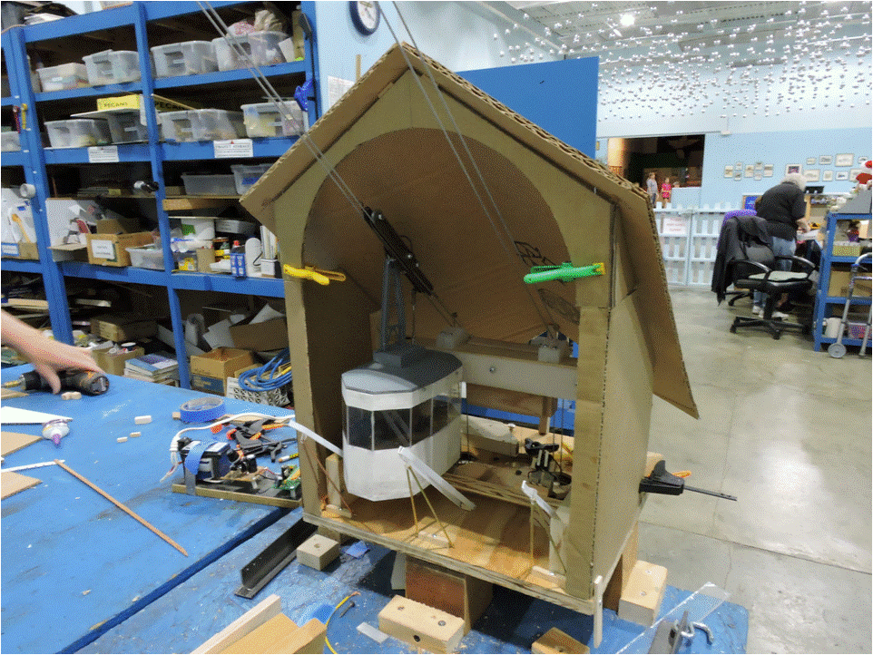 |
| Figure 6. Lower Station Mockup |
Having learned how to build the lower station building, the same techniques and some of the mockup parts, like the front arch and the roof, will be used for the construction of the upper station building.
Much remains still to be done, but we’re pleased with the progress to date. Stay tuned for future updates.
© 2018 Tom Bartsch
MVGRS Big Train Project Coordinator