
 Tickets
 Parties
 Shop
Shop Directions
#131 May Status Report
May 10, 2018
This month’s article continues the description of the EnterTRAINment Junction (EJ) layout’s aerial tramway, currently under development. This time, we’ll explore the design concept and how it’s being implemented mechanically and electrically on the tram cars. Figure 1 is a repeat of same Figure used last month to show what aerial tramway terminology means.
One of the key features of the tram design was to have lighting inside the tram cabins. That requires two electrical conductors, one positive and the other negative, to complete the circuit through the lighting in the cabin. One idea was to have the upper haulage rope (made of stranded wire) one polarity, and the lower haulage rope the other polarity. Unfortunately, because of the continual bending of the haulage rope’s wire around its pulleys, there was a high likelihood that metal fatigue would eventually cause the wire to fail. Another concept was that the haulage rope provides one polarity and the track cable provides the other. This still suffers from the fatigue potential and adds the potential for contact between a swinging or bouncing bare haulage rope and the track cable causing a short circuit. So, the concept that was selected would be much like our trains: two track cables for each car (one for each polarity, spaced an appropriate distance apart – i.e., 3/8 inch), with the truck providing the electrical pickup and feeding it inside the cabin.
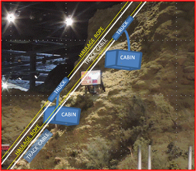 |
| Figure 1. Aerial Tramway Terminology |
This concept required the truck to have two separate electrically isolated sets of rollers, which would need some flexibility to pivot around a central support axis perpendicular to the track cables. This would allow the roller sets to adjust for a change in cable angle above and below the points of application of the car’s load on the track cables. Each roller set would have two metal wheels, aligned to run along its track cable, providing redundant electrical contact. Figure 2 shows the truck on the wires of the test fixture. The fixed-length strut, between the lower roller set of the truck and the cabin roof, prevents the cabin from swinging back and forth. On the actual tram, this would have been a variable-length damper, needed to eliminate or reduce swinging of the cabin and to accommodate the changing angle of the track cable as it crossed over intermediate cable support towers. EJ’s tram has no such towers, so the track cables remain at almost a constant angle relative to the ground along their entire span.
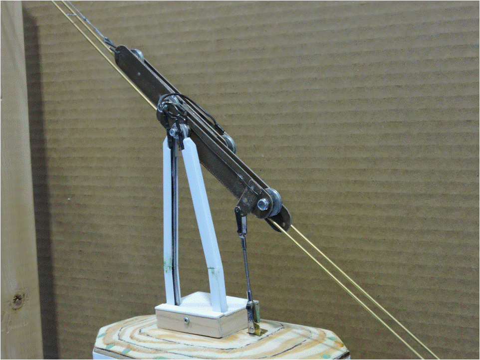 |
| Figure 2. Aerial Tram Truck |
The cabin hanger, which connects the truck to the cabin was made from a length of 1/8-inch steel wire, bent to the appropriate shape with a vertical “loop” at the top and two horizontal loops at the bottom to allow bolting to the truck and to the cabin respectively. Since the round cross section of the hanger wire did not match the appearance of the prototype, some Plastruct® I-beam material was used to give the hanger a more prototypical look, hiding both the hanger wire and the electrical wire for the lighting.
Figure 3 shows an expanded view of the parts of one of the trucks. The central spine has the connection points for the upper and lower haulage ropes. The lower roller set of the truck, with its connection for the stabilizing strut, is at the right. The upper roller set is at the left. The spine and side panels are cut from thin fiberglass sheet to provide electrical isolation of the two roller sets. The rollers are pulley sheaves with metal ball bearings. A wire, which connects the front and rear rollers electrically, runs from under one axle nut to the other (this can be seen on the rear roller set in Figure 2). The wire then continues to a plug which fits into one of two sockets near the top of the cabin hanger. The pivot for the wheel sets is on a single axle through the center of the central spine and offset to the front and rear of the two roller sets (the pivot axle for the roller sets runs through the nut-washer spacers shown sitting on top of the left of each of the pair of roller-set side plates. There were two primary reasons why the wheel sets were staggered front to back. The first was to avoid having the bolt heads of the axle bolts at the same fore-and-aft location opposite the central spine. This made for a narrower truck which allowed closer spacing of the track-cable pair. The second reason was to make the truck look longer, consistent with the appearance of the truck on the Cannon Mountain prototype.
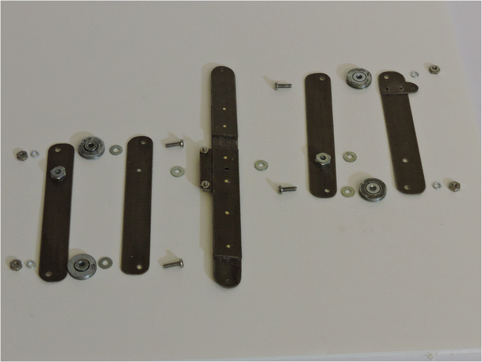 |
| Figure 3. Parts for the Tram Car Truck |
The cabin lighting consists of four 3-LED strips mounted to the underside of the cabin roof. In addition, a variable resistor and a bridge rectifier were added at the input end of the parallel lighting circuit. This allows the intensity of the light to be reduced by the resistor, if necessary; and the rectifier makes the car insensitive to the electrical polarity of its two track cables (Figure 4).
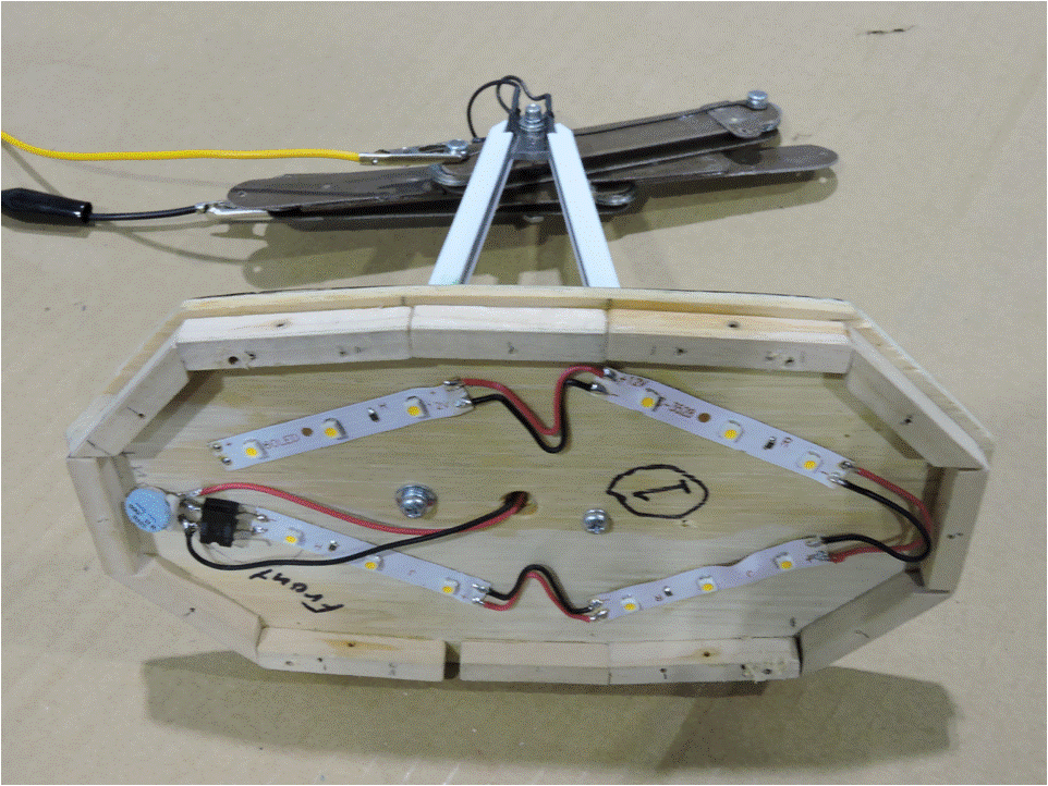 |
| Figure 4. Tram Cabin Lighting |
A thin sheet of white plastic is used as a diffuser to spread the light of the LEDs, make it less harsh, and prevent the LEDs from being seen directly (Figure 5).
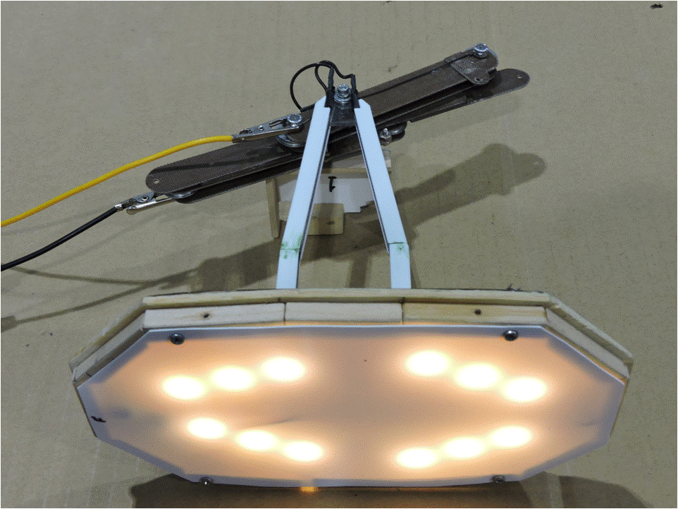 |
| Figure 5. Tram Cabin Lighting Diffuser |
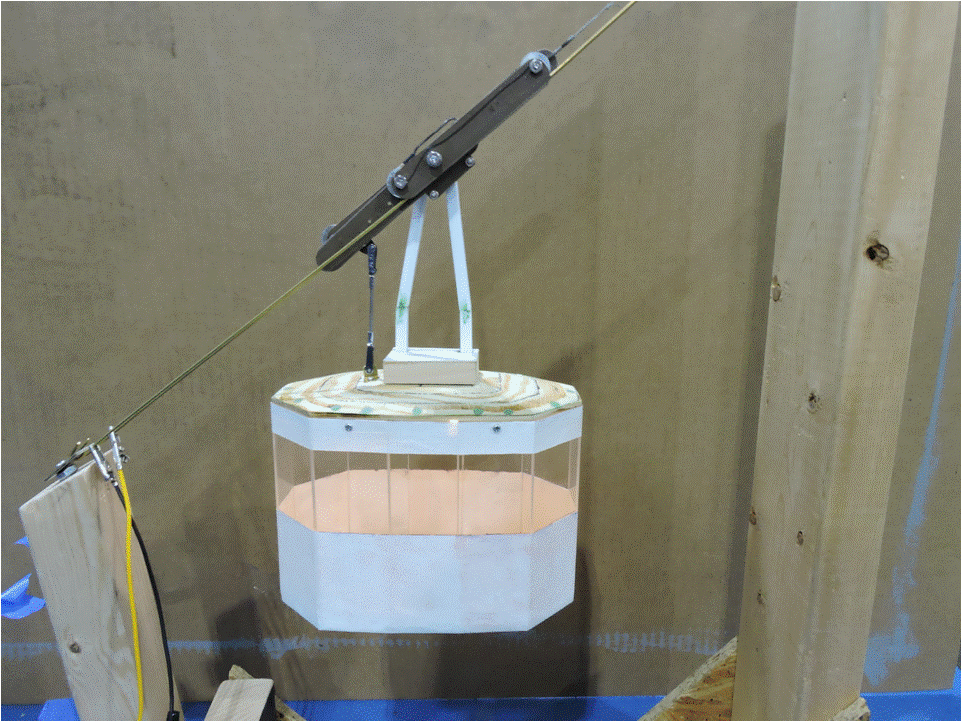 |
| Figure 6. The Lit Tram Car on the Test Fixture |
With the car assembled and suspended from the test fixture’s track-cable wires (Figure 6), the lighting system works as intended when power is supplied to the track cables. The positive and negative inputs to the wires could be swapped and the lights would still work. The test fixture was designed to allow tightening of the track-cable-surrogate-wires sufficiently to reduce the sag in the wires at the point where the tram car is suspended. Even with a fair amount of tension in the wires, the ~12-ounce car causes some deflection and some small change of angle relative to level and to each other of the track-wire section above the truck and the section below it.
A lot more remains to be done, especially on the upper and lower tram stations, so, stay tuned. More reports on this subject will follow.
© 2018 Tom Bartsch
MVGRS Big Train Project Coordinator