#120 June Status Report
June 12, 2017
This article explores the details of a recently added feature in the Early Period logging area of the EnterTRAINment Junction (EJ) layout (Figure 1). It is what’s called a “Tight Skyline Logging System.” It’s located across the EJ aisle from the lakeside town with the steamboat.
The purpose of the Skyline was to pick up harvested logs, preferably clear of the terrain, from near where they were cut, and move them to a location where they could be transported by other means or could be processed. The tight system uses a Skyline which is not adjusted to raise and lower the load. This is opposed to a similar system, called a “Slack Skyline” whose tension was released to lower the load and tightened to raise it.
 |
| Figure 1. Skyline Logging System |
 |
| Figure 2. Tight Skyline System Schematic |
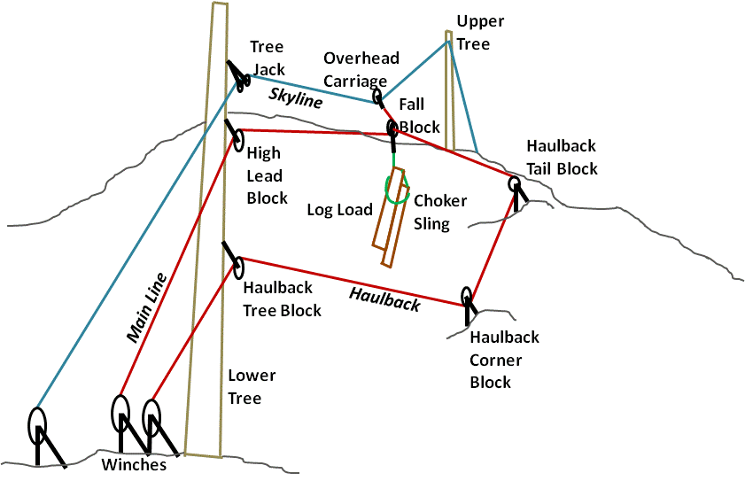
Figure 2 is a schematic of the functional rigging of “Tight” system. It was operated from winches located where there was mechanical power to haul on the lines (at the time of the Early Period, this was usually a steam-driven donkey engine, seen in the foreground of Figure 1). Because of the high loads, the rigging was usually made of steel cable. And, to reduce the bending loads on the trees used to elevate the Skyline, static guy wires to the ground from near the top of the trees were used to keep the top in position. Also, sometimes guy wires were attached near the center of the trees as well, to keep the tree from buckling under the increased compressive loads applied by the rigging. (The guy wires are not shown in Figure 2.)
A Choker Sling (made of cable or chain) was wrapped around the log load and attached to the Fall Block, which hung from the Overhead Carriage. The Carriage would move along the Skyline driven by the tensions applied to the Fall Block by the Main Line and the Haulback. The block end of the Haulback line was fixed to the Fall Block. The Haulback was used to bring an empty Fall Block and sling back to the harvesting location and to control the position of the Carriage along the Skyline when the Fall Block was loaded. The Main Line was used to raise the load and to pull it toward the winch location. Because the Main Line ran around the Fall Block up to the Carriage, increasing the tension between the Main Line and the Haulback would raise the load relative to the Carriage, decreasing that tension would lower the load (this is the essence of the “Tight” system). That meant moving the load along the Skyline required good coordination between the release of the Haulback and the hauling in of the Main Line, or vice versa, in order to keep the load suspended above the terrain.
If the Haulback Tail Block was offset to the side of the Skyline (as in the schematic and in the EJ model), the tensions between the Main Line and Haulback could be used to reach and haul up logs that were not directly under the Skyline, but offset from it in the direction of the Tail Block. Additionally, if the tension on the Skyline was adjustable (it is not in the EJ model), farther offsets toward the side of the Tail Block would be possible, though this would make it more like a Slackline system.
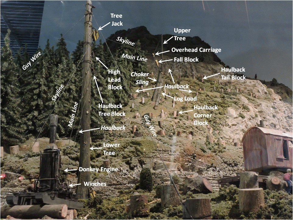
Figure 3 repeats Figure 1, but this time with the details labeled, using the terminology from Figure 2 and the description above.
 |
| Figure 3. EJ’s Skyline Logging System Labeled |
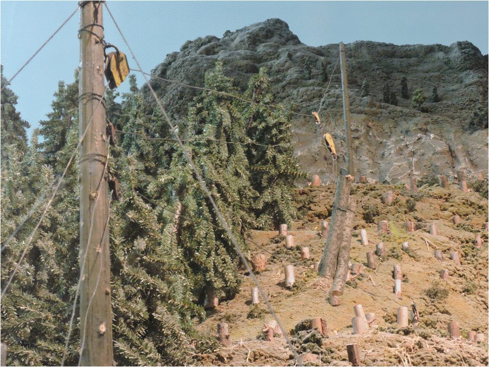
Figure 4 provides a detailed view of the Skyline and the log load hanging from it. Unfortunately there is not a lot of contrast in the colors of the foreground and background items, making some difficult to see.
 |
| Figure 4. Details of the Skyline and Log Load |
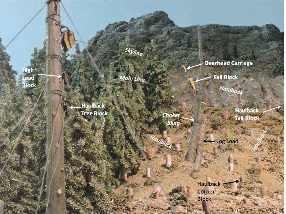
Figure 5 provides labels to help identify the significant items in Figure 4.
 |
| Figure 5. Skyline and Log Load Details Labeled |
EJ’s model provides a fascinating look at one of the many log transporting techniques used by the logging industry. Check it out the next time you visit EJ.
If you’re interested in more details about these kinds of systems for your own modeling or to satisfy your curiosity, the following websites offer additional insights and information:
https://forestry.mosaictraining.ca/logging_diagrams.html
and
https://www.osha.gov/SLTC/etools/logging/manual/yarding/example_systems.html.
© 2017 Tom Bartsch
MVGRS Big Train Project Coordinator

 Tickets
 Parties
 Shop
Shop Directions