
 Tickets
 Parties
 Shop
Shop Directions
#63 Status Report
June 8, 2012
One of the most common trackside details one can find in railroading are the crossing gates at grade crossings, where roads cross active tracks. The EnterTRAINment Junction (EJ) layout has needed these details for quite some time, but implementing them into the layout in the appropriate way, properly configured and animated, required special attention, modeling talent, engineering skill, and a bit of time. Those four elements have come together recently to produce outstanding results. Functioning gates were installed for the first time on the layout at the crossing from the Modern City’s central boulevard into the parking lot of the main underground subway station (Figures 1 & 2).
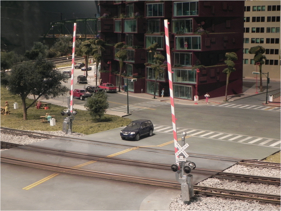 |
| Figure 1. Crossing Gates Up |
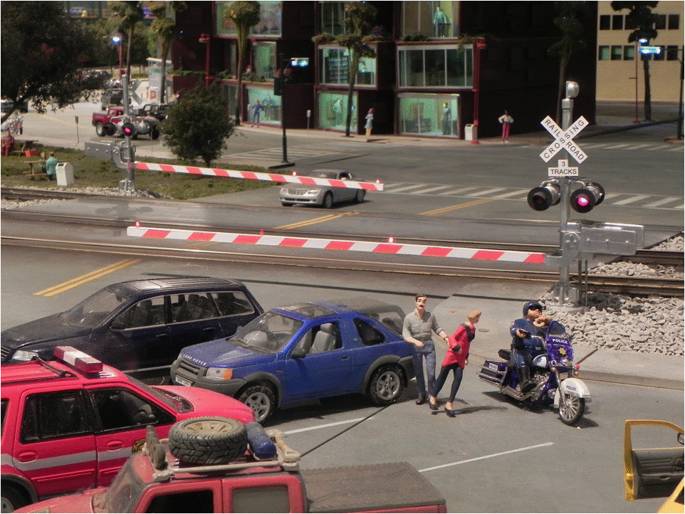 |
| Figure 2. Crossing Gates Down |
The physical appearance of the gates, crossbucks, and flashers was beautifully reproduced (Figure 3),
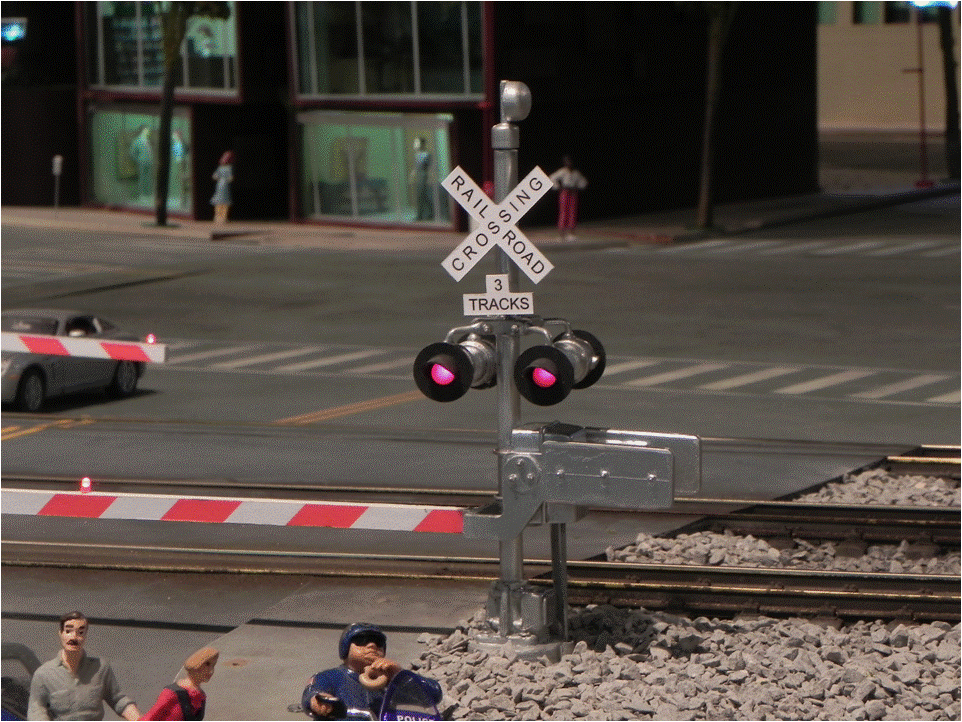 |
| Figure 3. Detail of Gates. Crossbucks, and Flashers |
The mechanics of actuating the gates was a bit more of a challenge than the above-ground appearance. That challenge was superbly met by the relatively simple and elegant mechanical design shown in Figure 4. A gear-motor drives a jackscrew which moves a threaded box beam up and down. The beam is kept from rotating by sliding against a plastic rub strip. A threaded control rod, fastened with nuts at the proper location, provides an adjustable connection to the gate above. Two limit switches, each on adjustable mounting plates, set the limits of the motion of the beam, one for up, the other for down. Fortunately there was adequate space under the layout for mounting and access to the mechanism at the needed location.
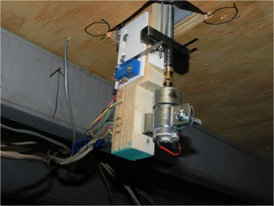 |
| Figure 4. Crossing Gate Actuator |
The real challenge came from accurately modeling the timing of the animation, making the lights flash and raising and lowering the gates, all consistent with the passage of the trains through the crossing. At this initial installation location, the challenge was three times as hard, because three tracks controlled the gates’ operation, each one triggering a closing and opening for each passing train, but with the potential that the opening control function could be superseded by the passing of a train on one or both of the other two tracks at nearly the same time.
To get this to work correctly required a computer, a set of sensors, and some reliable triggers to activate the sensors. The triggers are magnets, one on the first locomotive of a train and the second on the last car of the train. The magnets are a normal part of EJ’s train control system, so the gate system sensors needed to be able to react to the ones already installed. There are two sensors in the track, the closing sensor far enough away to allow the gate to close before the locomotive, at its normal speed, arrives at the crossing, and the opening sensor just beyond the crossing (shown in Figure 5) to open the gates immediately after the train has passed. It requires both proper logic and timing to have the system react only to the locomotive on the way toward the crossing and only to the last car after passing the crossing. And in case a sensor is not correctly detected, the system must be able to reset not later than the passing of next train. With a fair amount of programming work and some off- and on-layout testing, the system is now up and operating, and magnificently so.
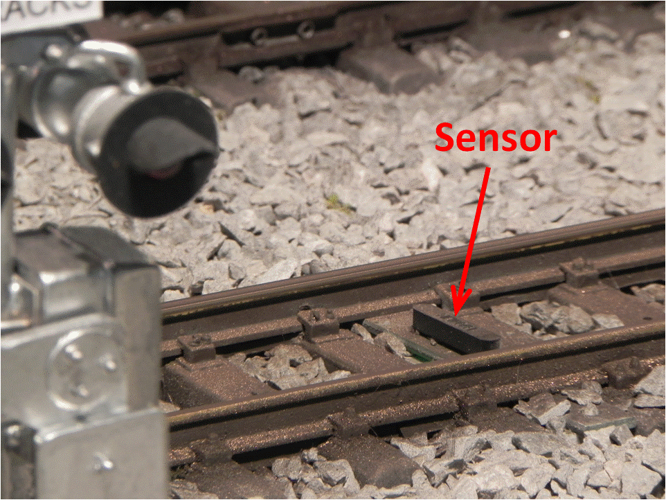 |
| Figure 5. Train Sensor |
The critical component of the crossing gate system to make it all work correctly is the controller, shown in Figure 6. It contains the computer on the green circuit board, a sound chip to provide the warning bell sound, an electronic flasher to drive the flashing lights, wiring connectors (for all of the sensors, gate actuator power, lights, and speakers), and a set of relays to transfer the correct polarity of power to the two gate actuators.
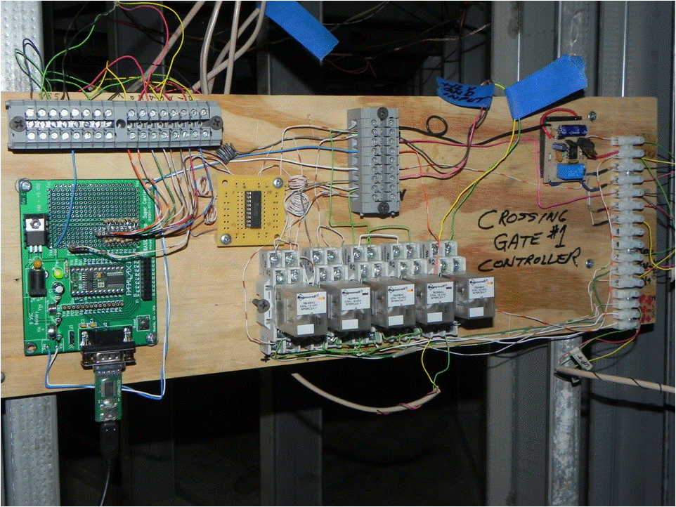 |
| Figure 6. The Crossing Gate Controller |
The combination of the physical modeling of the gates and signal posts, the mechanics of the gate actuation, and the complexity of the control implementation make this another example of the excellent modeling and superb engineering that is the hallmark of EJ volunteers’ work. What you see on the layout is just the tip of the proverbial iceberg. Hopefully this limited view of more of that “iceberg” will help you to better appreciate the magic both seen and unseen that makes this layout so special.
© 2012 Tom Bartsch
MVGRS Big Train Project Coordinator