
 Tickets
 Parties
 Shop
Shop Directions
#153 April Status Report
April 30, 2020
The previous report (Part 152) looked at the track wire and haulage rope connections with EnterTRAINment Junction’s (EJ’s) Upper Aerial Tram Station. In this report, I’ll show how those connections transition their functions through the station’s structure and how the external building interfaces with that structure.
Figure 1 is just a reminder of what the Upper Station looks like as installed with its interior lighting illuminated. In keeping with our normal policy, that no lighting LED should be directly visible by the EJ customers, two 3-LED lighting strips were installed on top of the beams above the station’s side windows, and three strips were installed behind the upper arch of the front wall. All LEDs are facing upward or to the rear, out of EJ customers’ line of sight.
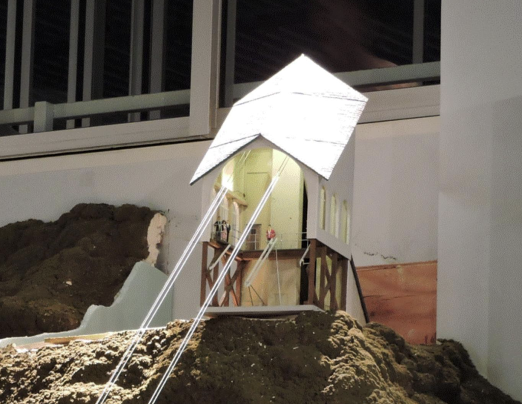
Figure 1. Upper Station With Interior Lighting
Figure 2 shows a view of the track-wire and haulage-rope connections to the crosswise 2×4, which is fastened with three screws to the gray vertical 2×4 post (leading downward in the lower center of Figure 1). This transfers the 25-pound tension from the four track wires into the station structure. The two alligator clips and wires carry the 12-volt lighting power from the track wires into the station.
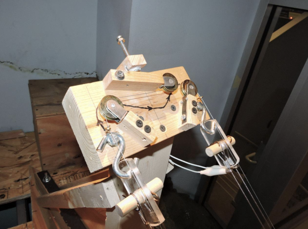
Figure 2. Upper Station Track Wire and Haulage Rope Attachments
Figure 3 shows the station structure from behind. The track-wire connection block is shown near the upper right, with the 2×4 vertical post going down to the station Base plate. Leading from the bottom of the vertical post on the base plate toward the plate’s rear point is the black-topped 2×4 horizontal beam. Both the post and the beam are screwed onto the Base plate from below the plate. Diagonal struts screwed to the sides of the post and beam connect the top of the post with the back of the beam and function as the primary carriers of the track-wire tension from the top of the post to the back of the horizontal beam. The Base plate is screwed to the EJ shelf with a screw just in front of the vertical beam. This is the pivot point around which the station was aligned with the lower station. A second screw, between the back end of the horizontal beam and the Base plate’s point, fixes the station’s alignment. These two screws, while important for positioning the station, were not meant to be the carriers of the track-wire load into the EJ shelf. That is done by the hold-down tie rod. The white wires from the alligator clips shown in Figure 2 were routed to the back of the post to a bridge rectifier which takes electricity of either polarity and produces the correct positive and negative inputs required by the station’s LED lighting, regardless of which track wire each clip is attached to.
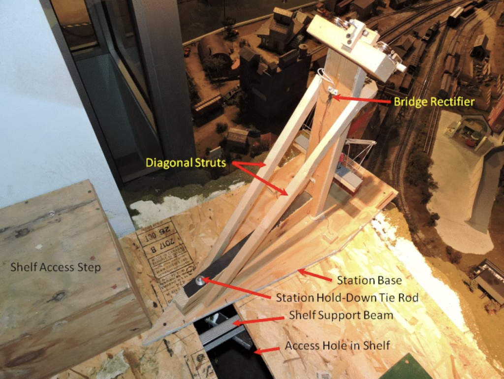
Figure 3. Upper Station Structure Rear View
The very solid construction of the Upper Station structure makes it act like a single lever with its pivot point at the outer edge of the EJ shelf. The tension from the track wires not only wants to pull the station off the shelf, but also rotate it around the shelf edge, trying to raise the rear of the structure. A downward load at the rear of the station is needed to counteract that torque. The shelf is supported by steel 2×4 beams spaced 16 inches apart (Figure 4). By placing a 2×2 beam crosswise underneath the two most adjacent shelf support beams and bolting it to the rear of the station’s horizontal beam, a very strong downward load can be applied to the rear of the station. In order to install the under-beam support, an access hole was provided in the EJ shelf. A piece of ¼” threaded steel rod was solidly bolted to the under-beam support so that it and the beam could be manipulated as a unit through the access hole and the threaded rod could be inserted through a hole in the station Base and horizontal beam. The crosswise beam was positioned so that it would rest against the bottom of the two shelf beams on either side of the station. A washer, lock-washer, and nut were then installed on the upper end of the rod, and the nut was tightened to lock the station firmly to the shelf structure. To prevent the beam-rod unit from being dropped accidentally during installation, a string was tied to the rod and to the manipulator’s hand until the installation was complete. After installation, a cover was then placed over the access hole.
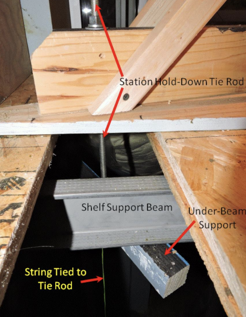
`Figure 4. Upper Station Hold-Down
To allow easy access to the internal works of the Upper Station, the station building was made to be easily removable. The building comes in two parts, the main platform shelter and the cover for the diagonal structural struts at its back. The strut cover must be removed first, then the platform shelter. Since the station lighting is contained entirely in the platform shelter, some means was needed to provide it with the positive and negative feeds from the bridge rectifier. Also, some means was needed to correctly locate the building on the Base platform. Blocks were attached to the Base which fit exactly into the rear corners of the building (Figures 5 and 6). Secondary blocks were installed to fit into the lower front of the building’s side frameworks. To install the building, it is tilted slightly to the rear, lowered over the structure, and its back corners are placed against the backs of the rear alignment blocks. Then the building is rotated forward until it sits level on the base. The rear alignment blocks were also used to hold the ends of the lighting wires with the attaching screw heads acting as contacts. Contacts in the building completed the circuit. This avoids the need to connect or disconnect a separate electrical connector for the lights when installing or removing the building.
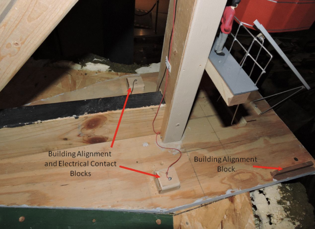
Figure 5. Upper Station Alignment Blocks
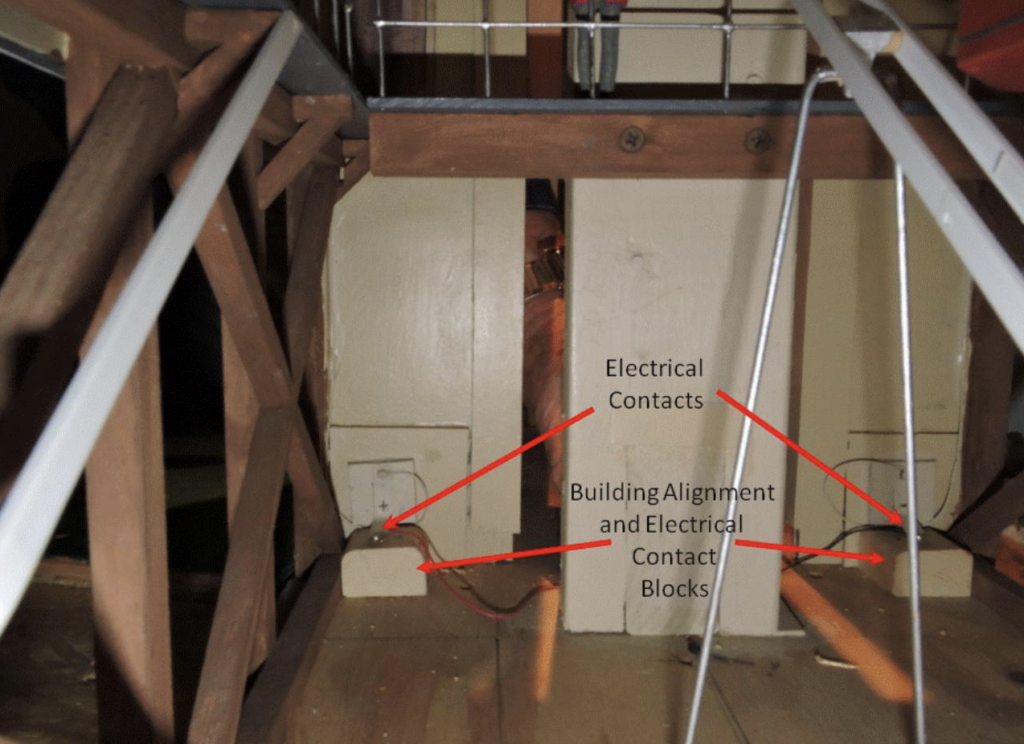
Figure 6. Upper Station Alignment Blocks and Lighting Circuit Contacts
Spring contacts made of thin brass sheet connected building’s lighting were mounted to the back wall of the building and aligned so that they contact the screw heads on the tops of rear alignment blocks when the building is properly seated on its base. A similar system is used on the Lower Tram Station as well. Note that the alignment blocks have rounded corners on top to help guide the building into position. This helps during installation, since it must be done “blind” from the rear of the building.
While we hope that the tram system doesn’t require a lot of maintenance, we know that some maintenance will be inevitable. We’ve tried to make it as maintenance-friendly as we could within the limitations of space and the need to make it appear as realistic as possible. Hopefully, needed maintenance will be rare and quick and easy to do when it is needed. As always, our objective is that this system will provide visitors with another of EJ’s marvels for their interest and enjoyment.
© 2020 Tom Bartsch
MVGRS Big Train Project Coordinator