
 Tickets
 Parties
 Shop
Shop Directions
#145 August Status Report
August 27, 2019
This month’s report describes the planning and beginning preparations for the installation of the Aerial Tramway on the EnterTRAINment Junction (EJ) layout.
As different as the upper and lower stations are in appearance, so different too are the characteristics of the two sites on which they will be located. Figure 1 shows the elements of the above-layout installation: the two stations, the cables between them, and the access road to a parking area for customers near the lower station. Because of the relative difficulty in accessing the upper station location (on a shelf outside one of the EJ mezzanine’s windows) the tram functional design was aimed specifically at minimizing any tram maintenance at that location. The only adjustment that can be made at the upper station is the operating length of the upper haulage rope that pulls the cars up their respective track cables. This length determines where in the upper station the tram cars stop.
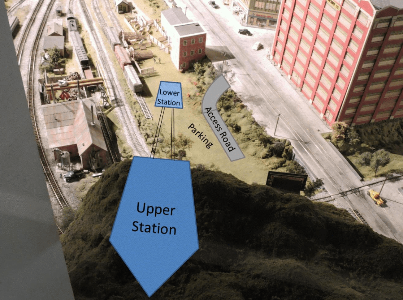
Figure 1. Aerial Tramway Installation Sites
The drive mechanism for the haulage rope and the tensioning system for the track cables are all located below the lower station, under the layout table, so it was necessary to determine where on the lower meadow the station could be located so that under-layout structure would not interfere with the tramway mechanisms. Determining the location of the lower station required building a map of relevant features both above and below the layout table. The first step in accomplishing this was to generate a common reference point both on top and below. This was done by simply drilling a hole near where the station would be located and inserting a wire down through it that could be seen below. Figure 2 shows the location below the layout and the wire with a blue tape “flag” at its end. A common feature above and below at some distance from the hole was used to provide a reference angle. That feature was the vertical beam that led from the floor below the layout up to support the corner of the mezzanine shelf. Using the point and the direction as the coordinate system, measurements to the relevant features could be made and coordinated for locations both above and below the layout.
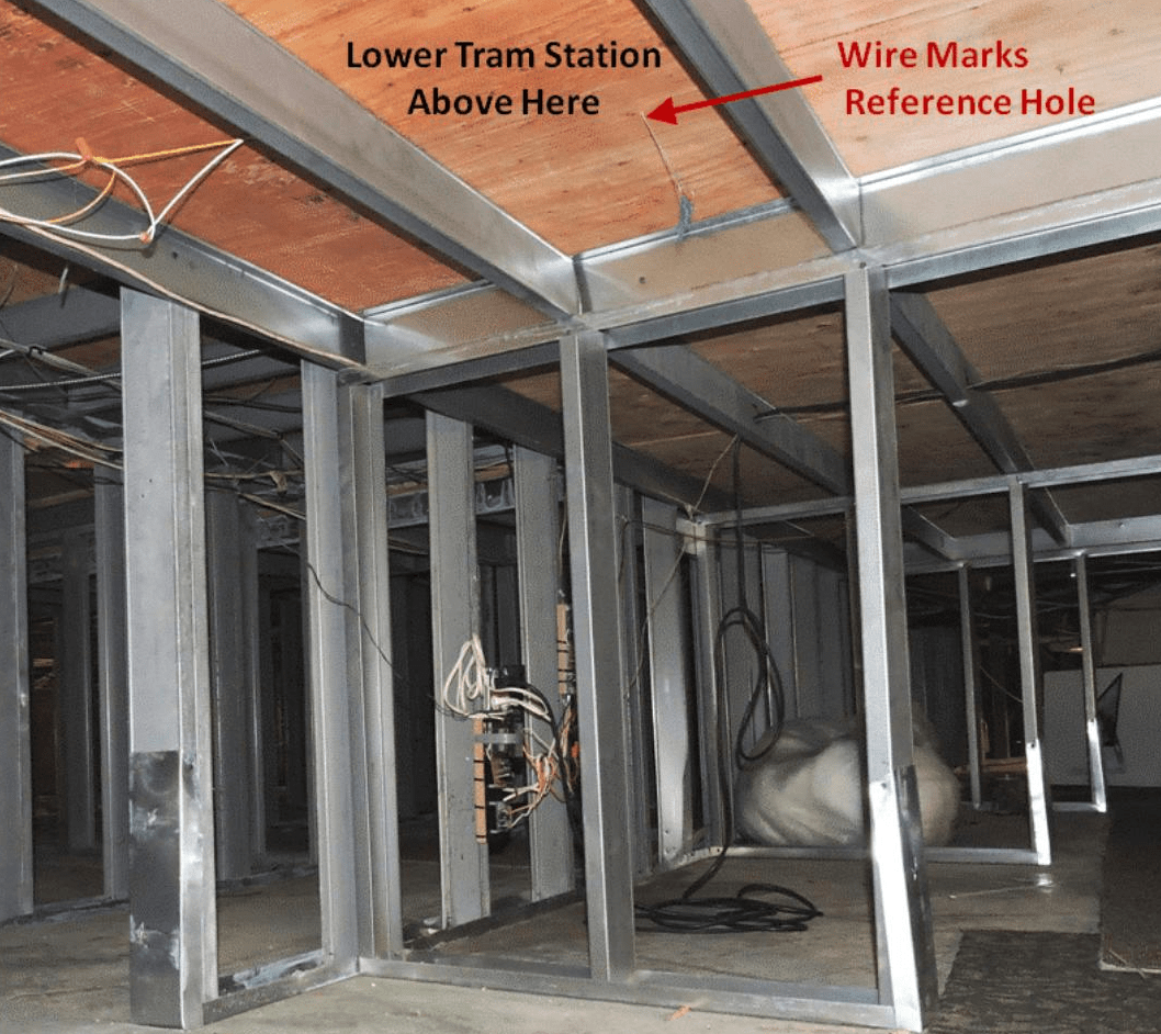
Figure 2. Lower Tram Station Location below the Layout
To put this all together, a full scale map was created on a large piece of cardboard (Figure 3). The station location could then be placed to avoid interferences and to give reasonable and believable clearances to the existing and planned layout elements.
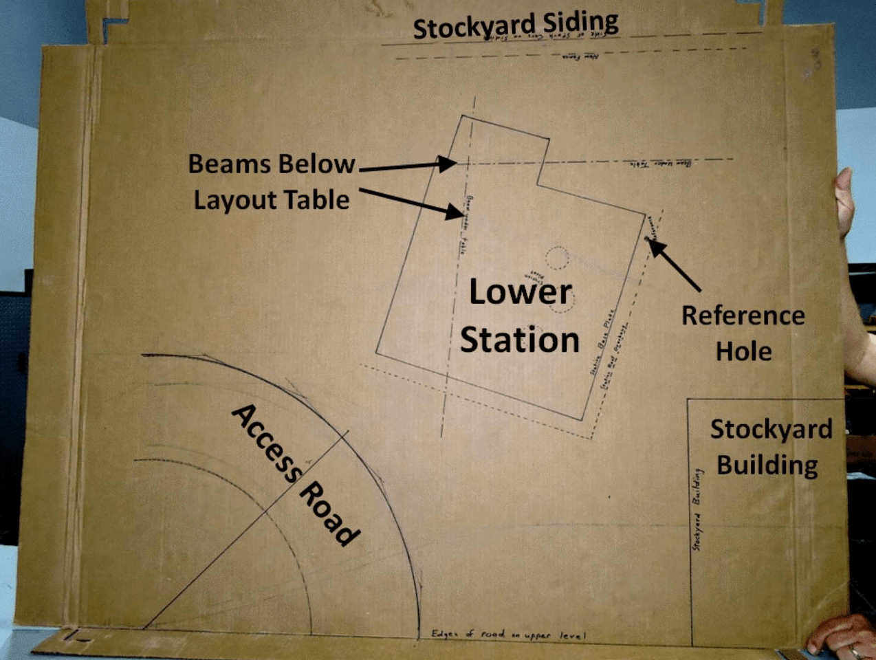
Figure 3. Lower Tram Station Site Map
In addition to the lower station, a realistic setting needs a way to get customers to the tramway, and by way of the tramway up to the restaurant adjacent to the upper station. That requires a parking lot for customers’ cars near the lower station and an access road to get from the city street down to that parking lot. Figure 1 showed the route chosen for the road. It required a 90-degree curve (which had to be level) and a smooth transition into the downward slope at the top and a similar smooth transition out of the slope at the bottom. Also, since the layout may need to be walked on, there is some chance that someone would step on the road, so its underlying structure would need to be strong enough to support a persons weight. Figure 4 shows part of that structure supporting the level curve and the upper smooth transition. The piece of 1/8-inch Masonite ® used for the straight section of the road surface was held in place, bent to give the desired transitions for the desired height, and the transition pattern was traced onto the side of a 2×4, which was then cut to that shape. The road surface was then screwed to the cut edge of the 2×4 at the top and bottom ends to hold the road surface with its transitions in place. All of the structure is probably overkill, but it will surely be capable of supporting a person, if need be.
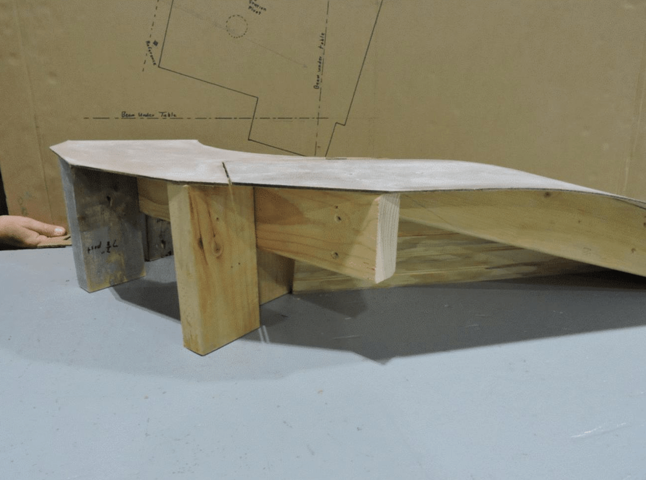
Figure 4. Tram Access Road Sub-Structure
To finish off the road, a simulated concrete block retaining wall is needed cover the down-slope side of the road. Because the plastic sheet simulating the blocks is flat with raised blocks and so not easily bent to the curvature of the road, the wall will have flat facets separated by vertical columns, as shown in the mockup (Figure 5). A ¾-inch high base and ¼-inch cap will allow efficient use of the sheets of simulated blocks while still allowing a scale two-foot-high safety barrier above the road surface. The existing scenery on the slope from the city street down into the meadow will be cut back and the edge of what is left will be tacked on top of the inner edge of the road surface. That way the amount of rework needed to the scenery between the city street and the access road can be minimized.
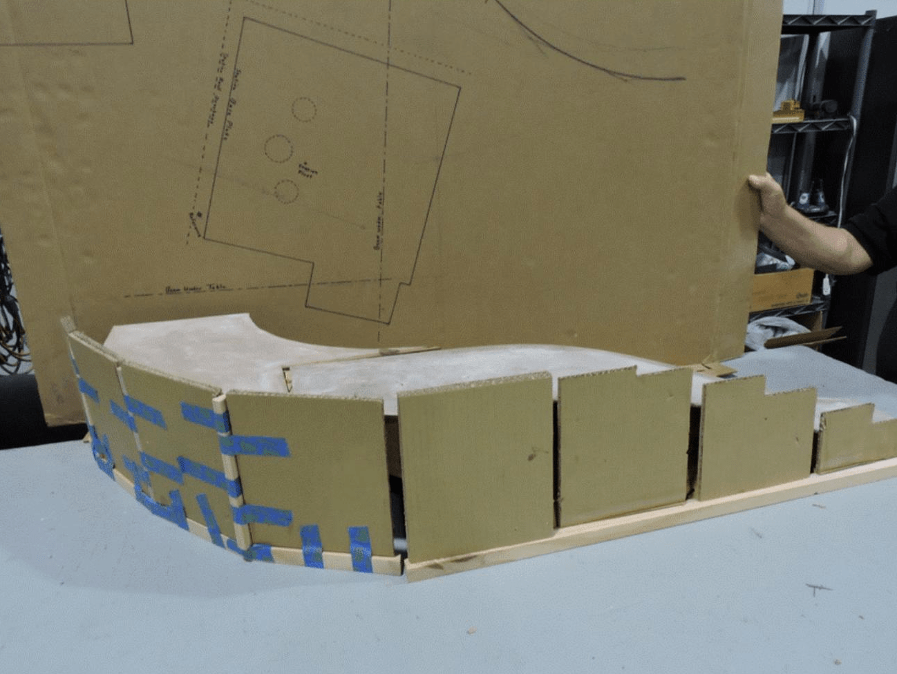
Figure 5. Tram Access Road Retaining Wall Mockup
Figure 6 shows the mezzanine shelf on which the upper station will be mounted at an angle from the left corner back. The rectangular hole is to allow installation of a structural anchor from the back of the station base to transfer the load from the tightly-tensioned track cables into the structure below the shelf.
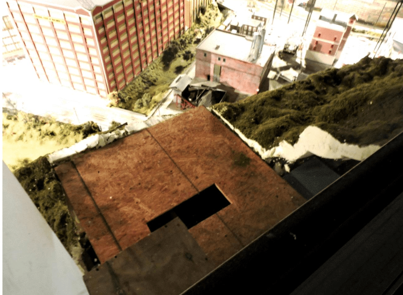
Figure 6. Upper Tram Station Site
The plan is to minimize the time required to install the lower station and access road so that the customers’ view of the Middle City is not significantly interrupted by the work in progress. The station buildings are decorative rather than functional. Their purpose is to hide the tram mechanisms, and, of course, to provide a realistic appearance. Once the station bases have been installed, and the tensioning system is in place under the layout, the more interesting (and still not fully planned out) installation of the track cables can be done. The last task will be the installation of the haulage ropes and the tram cars and the hook-up of the controls. There’s a lot still to do, so more reports on this subject will follow.
© 2019 Tom Bartsch
MVGRS Big Train Project Coordinator