
 Tickets
 Parties
 Shop
Shop Directions
#144 July Status Report
July 23, 2019
This month’s report looks at the final details of the EnterTRAINment Junction (EJ) aerial tram uninstalled system in its test fixture: the tram cars.
The finishing touches for the tram cars were painting, adding doors, adding passengers, and balancing the cars. Balancing was necessary so that each car would consistently avoid having unintended collisions with other elements of the system (i.e., the other car, the stations, and the sway guides). A key element of the balancing was adjusting the car’s center of gravity from side to side and front to back. It was decided to use the passengers as the adjustable weight to accomplish that. An oversized hole was provided in the bottom of the car shell (Figure 1). A bolt with a smaller diameter than that of the hole was used to attach an insert, to which the passenger figures were mounted. That “loose fit” from side to side and front to back, allowed some of the needed adjustment. Also note in Figure 1, the marking on the floor of the car indicating which end is the front (the uphill end) and which track cable pair on which the car was to ride (number 1, the left when viewed from the lower station). The interior bottom of the car is not readily visible from any locations available to EJ visitors, and the markings exist exclusively to assist EJ staff with assembly of the cars and with installation of the cars in the proper direction onto the proper track cable. Although the cars look alike, they are not identical. They have doors on opposite sides to match the station platforms that they serve, and the uphill end is distinctly different from the downhill end, primarily because of the angle of the track cable.
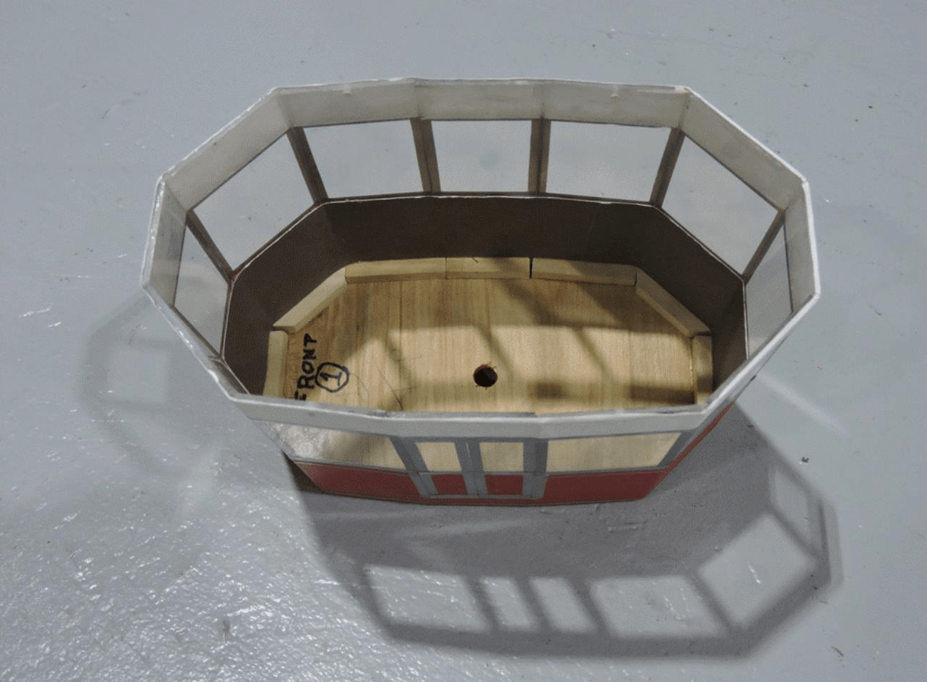
Figure 1. Left Tram Car Shell
The passenger insert includes the figures of the passengers, the central mounting bolt (attached firmly to the insert base), and spacers to raise the passengers to a realistic height in the car (Figure 2). The passenger on the far right has a substantial “bandage” on her right leg which fixes a break that resulted from overzealous pushing on the leg and its metal mounting rod during installation on the insert. But, as with the inside bottom of the car, this feature will not be visible to EJ customers.
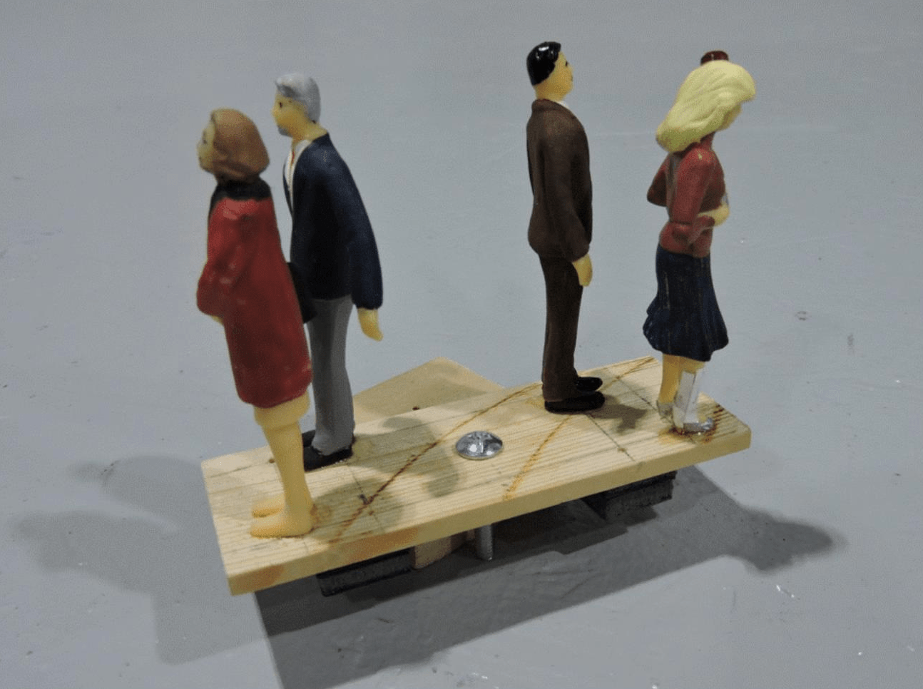
Figure 2. Tram Car Passenger Insert
Figure 3 shows the insert installed in the car shell (Figure 3). The car then had its roof, hanger, and cable truck installed and was mounted on a balancing fixture that simulated the angle of the track wire and the angle of the haulage rope. The insert’s position was then adjusted to achieve vertical sides and vertical ends as measured by an electronic level held near, but not touching, the car.
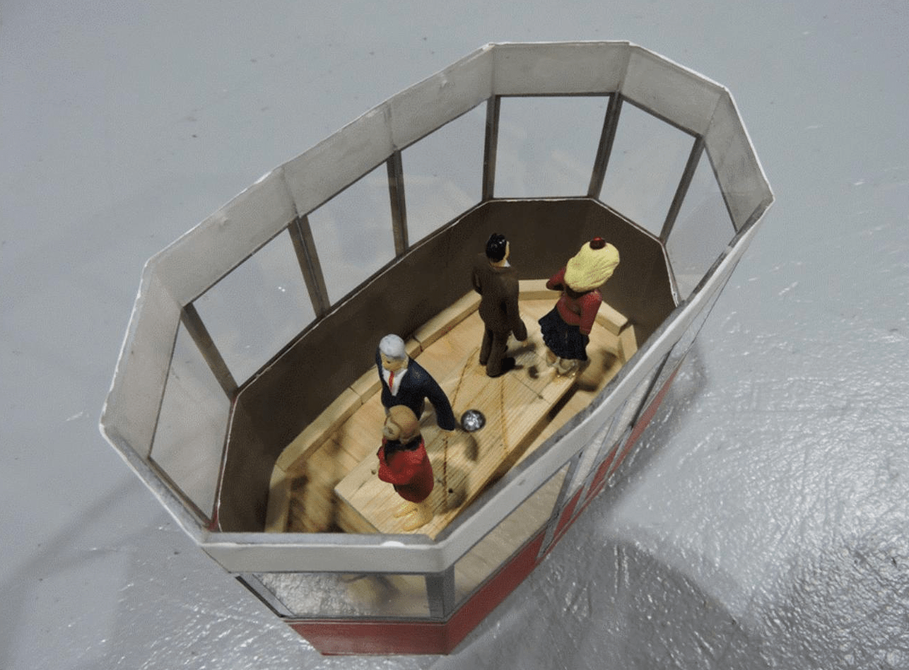
Figure 3. Tram Passengers Installed
Figure 4 provides a view from below of the tram cars passing each other. Because the haulage rope connects the cars to each other, they will always meet at the center of the track cable span. This view also shows the lighting in the cars and in the upper station. The brass plates on the bottom corners of the cars are protective wear plates located where the cars contact the metal fingers of the micro-switches that stop the cars when they arrive in their end positions in the lower station.
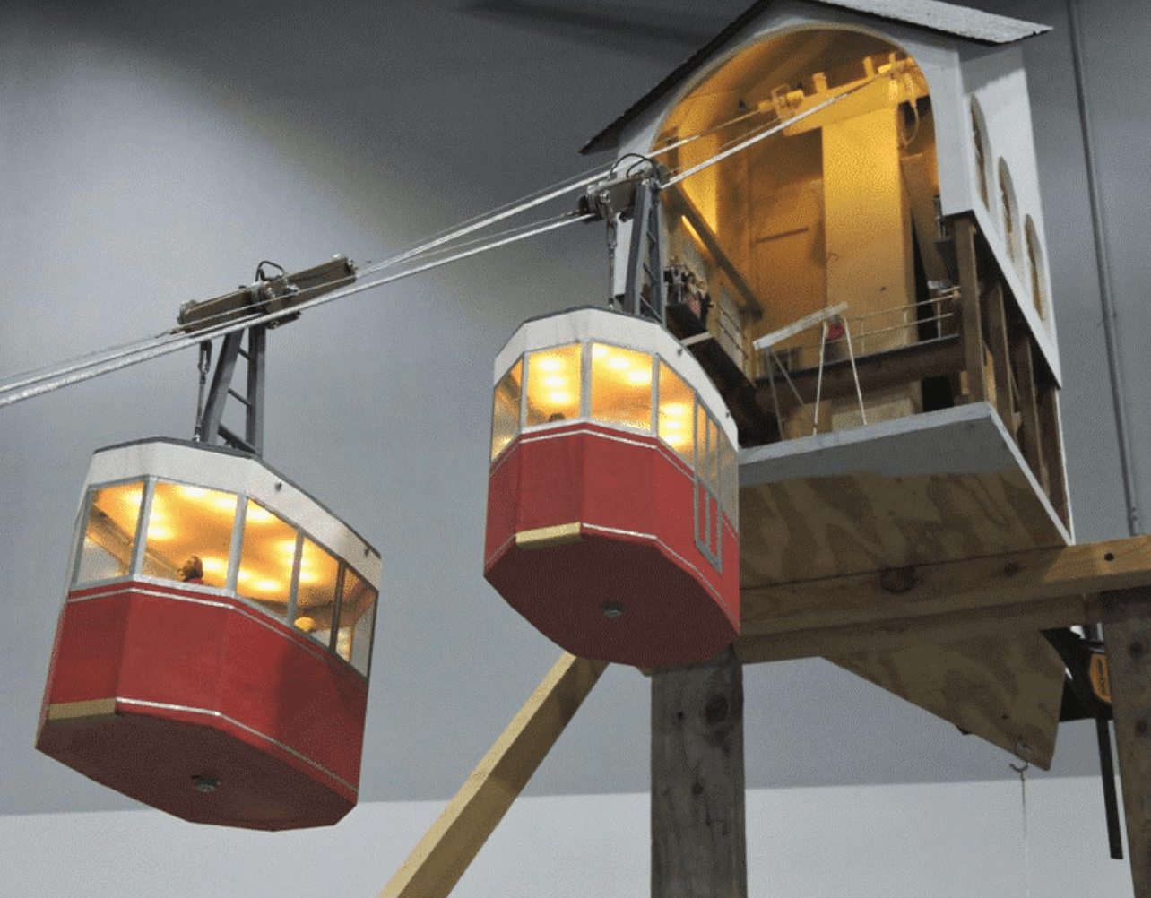
Figure 4. Tram Cars Passing Each Other
Figure 5 shows the cars just past their mid-span meeting. The doors, window frames, and decorative stripes were made with silver-colored automotive pin-striping tape, which usually has very good adhesive qualities and is very easy to use compared to masking and painting such stripes.
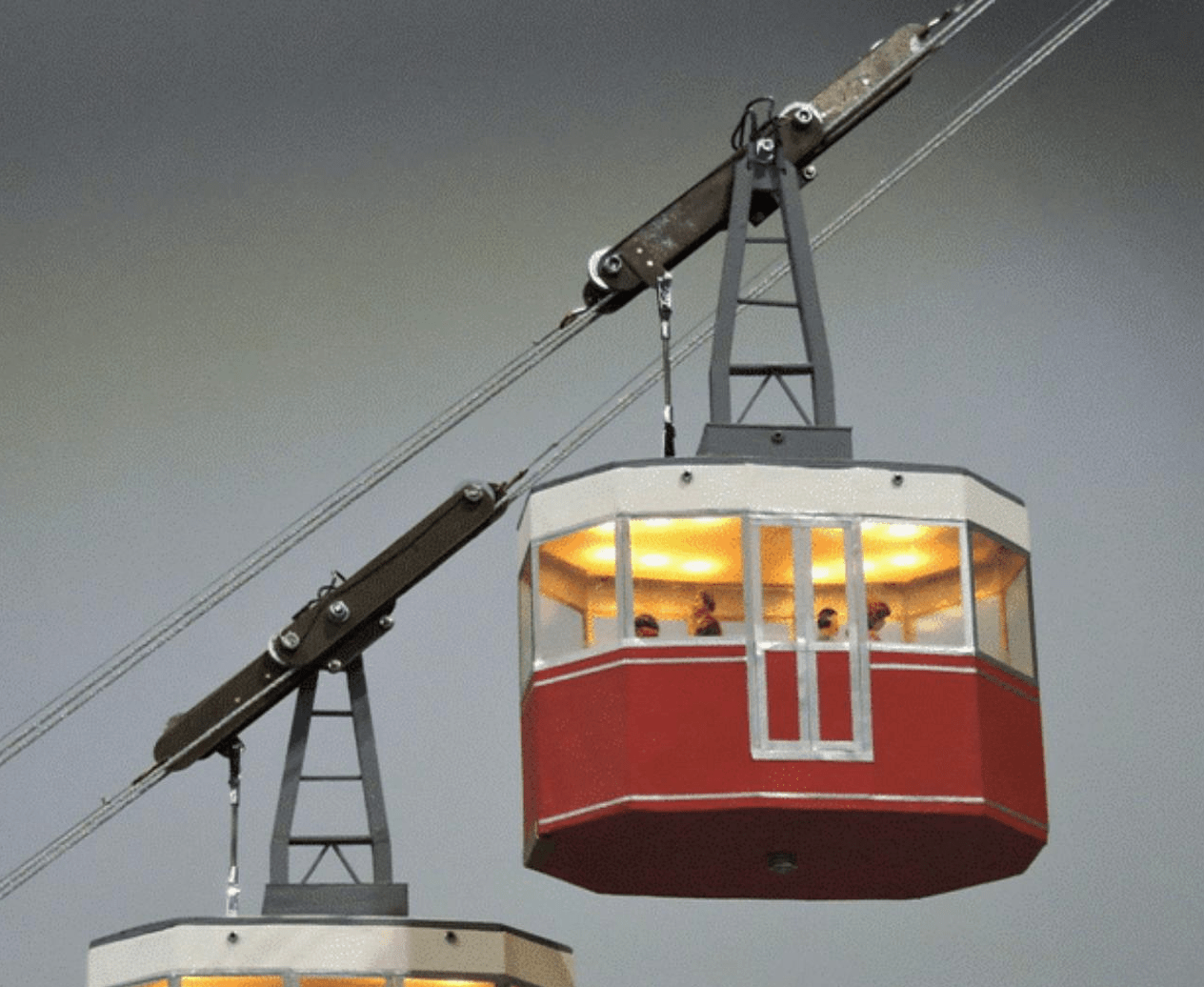
Figure 5. Tram Car Portrait
Figure 6 shows the right-side car approaching the upper station. The cars have doors on only one side, to match the location of the station platforms which they will exclusively visit in their runs.
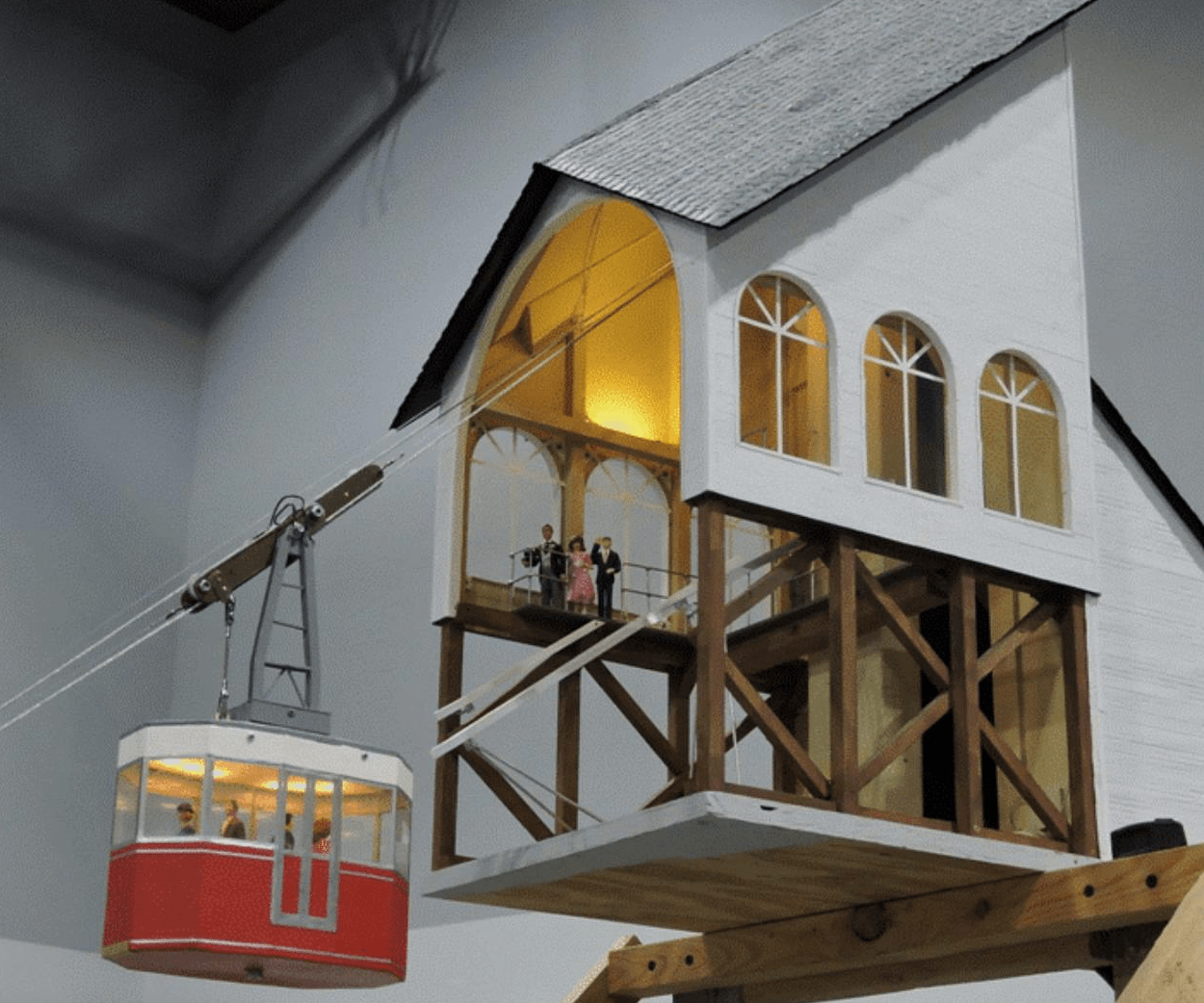
Figure 6. Tram Car Approaching the Upper Station
With the décor of the system completed, the next focus of activity will be the planning and execution of the system installation. This will include some fairly extensive modification of the EJ layout’s scenery.
in the locations where the stations are to be installed. More on that in future reports. Stay tuned.
© 2019 Tom Bartsch
MVGRS Big Train Project Coordinator