
 Tickets
 Parties
 Shop
Shop Directions
#130 April Status Report
April 10, 2018
This month’s article describes a new project being worked on for the EnterTRAINment Junction (EJ) layout. It’s an aerial tramway from the lower level of the Middle City, near the drive-in theater, up to the shelf on the cliff adjacent to the EJ mezzanine (Figure 1). The stylized image shows the basic concept and its location. The purpose of the tramway is to transport customers to and from a fancy restaurant, which will be located on the cliff-top shelf next to the tram’s upper station.
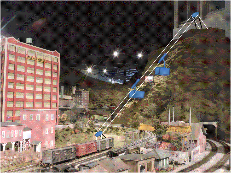 |
| Figure 1. Aerial Tramway Location (Concept) |
There are a number of ways to move people via a cable-supported or a cable-driven system. The incline behind the EJ roundhouse is one example of a cable-driven system. The sky-ride in EJ’s Coney Island is cable-supported and driven by that same cable. An aerial tramway has “cars” for the passenger hanging from a “truck” that rides on and is supported by a fixed cable or cables (called “track cables”). For efficiency, there are usually two cars connected via an upper “haulage rope” trough pulleys at the upper end of the tram and by a lower “haulage rope” through a drive mechanism at the bottom end of the tram. As one car moves up the tram, the other moves down, offsetting each other’s weight. In order to drive the cars up and down, the lower haulage rope to only has to overcome the frictions of the system and any difference in weight (depending mostly on the payload) of the two cars. This is called a “jig-back” system. The two cars will always pass each other going in opposite directions half-way along the length of the system (called the “span”). Figure 2 illustrates the terminology of the tramway planned for EJ.
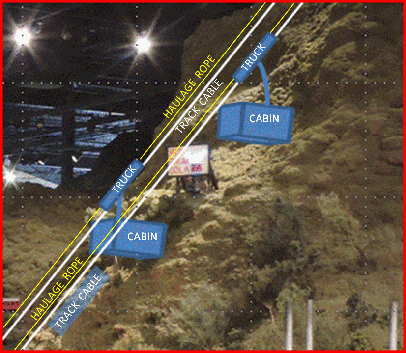 |
| Figure 2. Aerial Tramway Terminology |
Since EJ’s tramway will be in the Middle Period of the layout, an example was needed to provide guidance for the appearance and mechanical features. As usual, the Internet provided just what was needed. An aerial tramway, which opened in 1938, was located near Franconia, New Hampshire, called the Cannon Mountain Aerial Tramway (http://www.cannonmt.com/cannon-history.html).
With pictures in hand, the EJ volunteers began work, on the easiest part of the system first, the tram cars’ cabin. The Cannon Mountain tram used an eight-sided cabin, with windows all around, and a faceted roof, with the facets aligned with each of the side panels. The EJ design is intended to have interior lighting, and its interior needs to be accessible for the placement of figures of riders and for adjusting the balance of the cars. It was decided to make the cabin’s roof the main structural element, with the cabin sides and floor removable as a unit, “hanging” from the roof. All lighting is contained exclusively on the roof, and no electrical connections are needed into the lower part of the cabin. For simplicity, the entire height of the cabin sides are made of clear plastic, with opaque covers in areas where there are no windows. Flanges made of wood, attached to the roof and to the floor, hold the sides in position. The sides are glued to the floor flange but not to the roof. Screws through four of the side panels into the roof flange hold the cabin to its roof. Removing the screws allows the lower part of the cabin to be removed.
Figure 3 shows the parts of one of the two cabins. The center piece is the roof. For structural integrity, it was cut from ½” plywood. The facets were made by sanding it at the appropriate angles and locations on a belt sander. The black lines are the glue joints between layers of the plywood. They fortuitously provided good feedback about the progress and positioning of the facets during the sanding process.
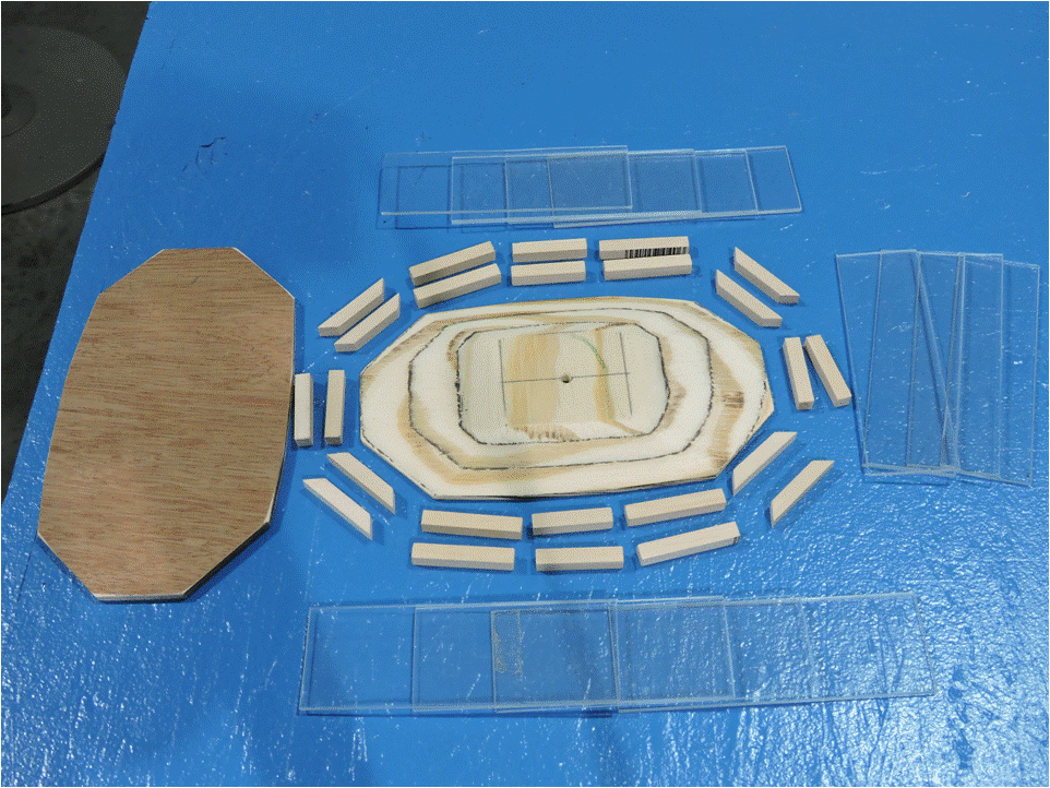 |
| Figure 3. Parts for the Tram Car Cabin |
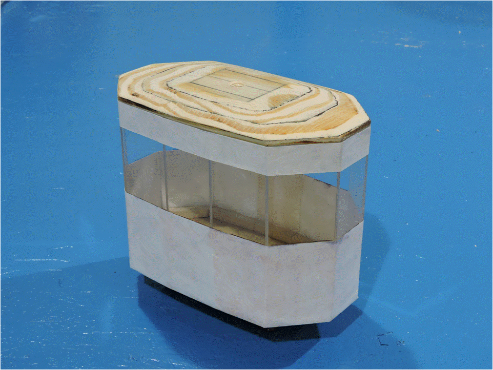
To assemble the cab, the roof and floor were attached to each other, screwed to a 2×2” post the same length as the cabin side panels. Side panels were glued to their respective lower flange piece, and then each side panels lower flange piece was glued to the floor. Each upper flange piece was glued to the roof to match the location of its side panel. Wax paper was placed over the top inside of the side panel to keep the glue from the upper flange piece from adhering it to the panel. Masking tape held the piece in place as each adjacent upper flange piece and side panel were attached in turn. The joints between each of the side panels were glued as the assembly proceeded, but those joints were not perfect and, because of the small surface area of contact, were structurally weak. Figure 4 shows an almost-complete assembly, missing only the roof flange for the panel at the right end.
 |
| Figure 4. Tram Cabin Assembly |
To strengthen the assembly and hold the side panels together much more securely than the edge-to-edge glue, Tyvek® strips were glued around the entire circumference of the cabin above the window location and below the windows (Figure 5). The lower Tyvek® strips were also folded under the floor and glued there to hold the side panels securely to the floor. The exceptional tear resistance of the Tyvek® makes it a very good structural strengthener for modeling. The material used for this assembly was from an old large-sized mailing envelope. Note the central post has been removed.
 |
| Figure 5. Tram Cabin Structural Assembly Complete |
Though not included yet in this figure, the structural integrity of the unit was further enhanced by screws holding the upper flange pieces to the roof. This was done so that glue-in-tension was not the only thing that held the lower cabin to its roof. Also not included yet are the screws that were used to attach the lower cabin to the roof. The next task was to build the trucks and provide a means to get electricity to the cabin for the lighting. More on that next time.
Stay tuned for more, as the EJ Aerial Tramway project continues to unfold.
© 2018 Tom Bartsch
MVGRS Big Train Project Coordinator