
 Tickets
 Parties
 Shop
Shop Directions
#31 Status Report
May 2, 2009
(The Tale of Two Cities – Part 1)
For this month I decided to take a slightly different approach to these articles, showing the progression over time of the development of two of the major scenic elements of the EnterTRAINment Junction layout, the two cities. That’s the reason for the title I borrowed from Charles Dickens. This month I’ll focus on the Modern City (Oakmore), for which I have a very strong personal connection, since our MVGRS team built most of it.
The design dates back to mid-2006. Our objective was that its plan be different from the rectangular blocks of the Middle Era City, and that a viewer should not be able to look through it from one side to the other (to hide how small in scale area it actually is). Also, the streets would slope up toward the center and back to add interest and to make the details on the streets more visible from the aisles. The initial planning model is shown in Figure 1.
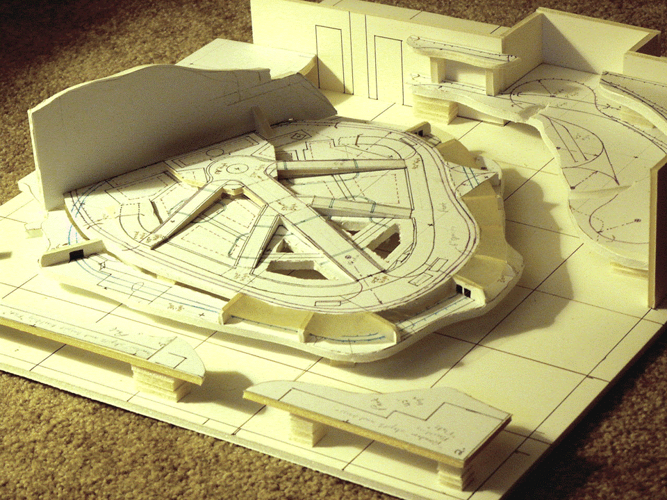 |
| Figure 1 Modern City Planning Model, 29 Aug 2006 |
At our first major open house, aimed at finding and recruiting volunteers, we’d transferred the design to the floor of the EnterTRAINment Junction building using masking tape. We provided both a map (on the easel) and an updated version of the model (on the chair) to show prospective volunteers where it would be located and how it might look when finished (Figure 2).
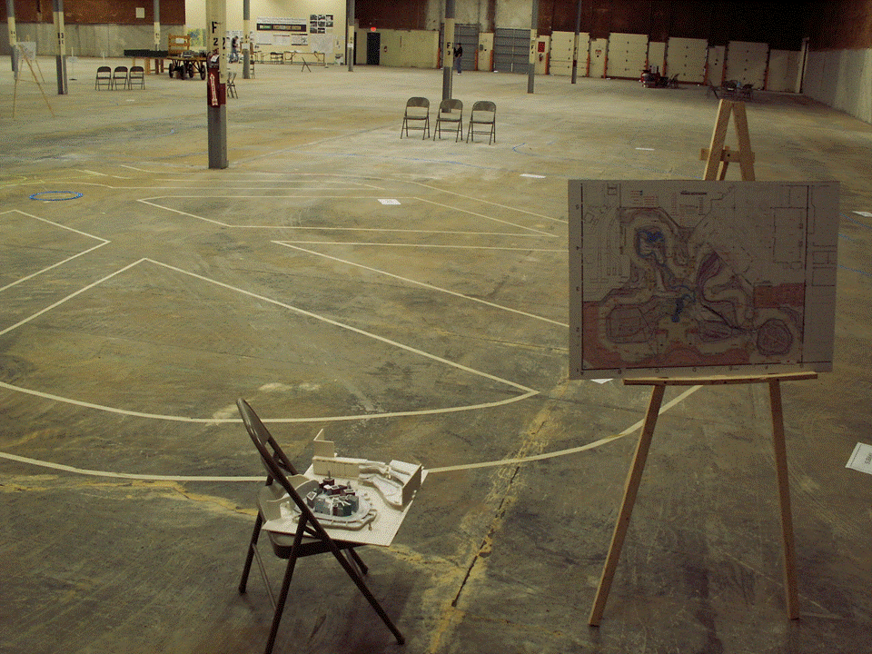 |
| Figure 2 The Volunteer Open House, 6 Jan 2007 |
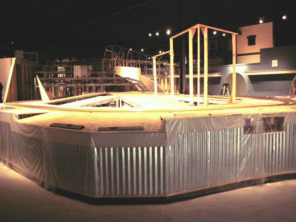
Not long after this, the contractors started working on the building, trenching, putting in plumbing and electrics, installing air conditioners, etc. The most important progress was the contractors building the table structures on which we would build the layout. By the time of the first volunteer appreciation dinner on 2 Dec 2007, the tables were up (Figure 3).
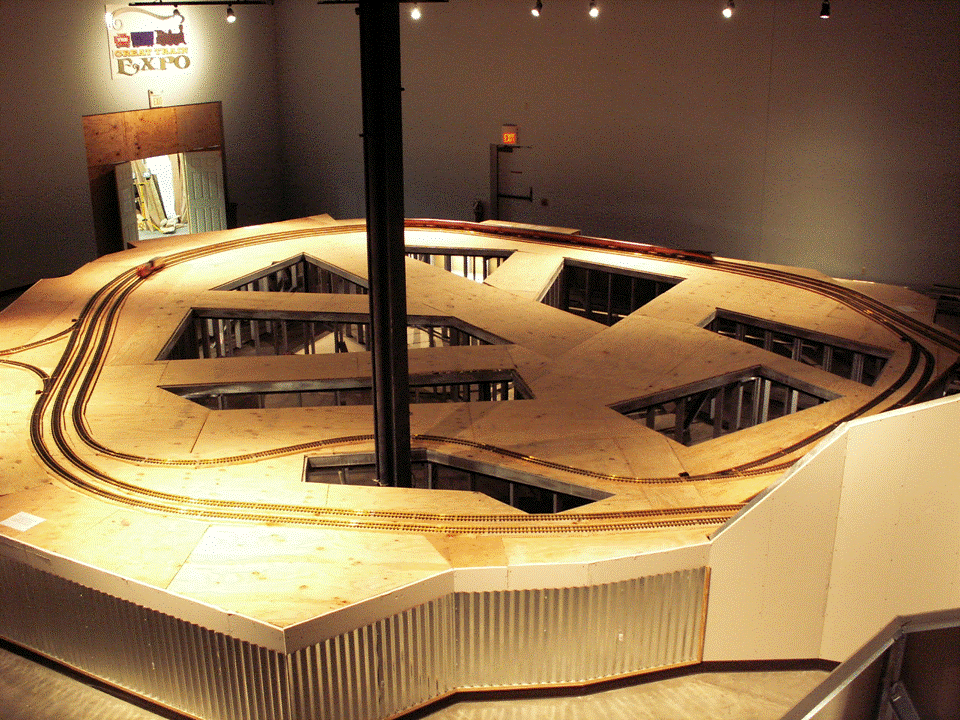 |
| Figure 3 The Flat Tables, 2 Dec 2007 |
The flat tables, however, were not ready for us to start construction, since the design called for the streets to slope up toward the mountainside that forms the back of the city. So, Ray Hughes and his crew went to work, and by the end of January, 2008, had raised the streets as the design dictated (Figure 4). The level area at the top of the sloped streets is one foot higher than the normal 54” table height.
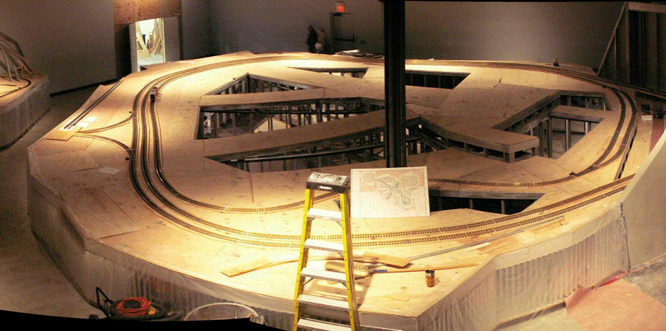 |
| Figure 4 The Streets Elevated, 23 Jan 2008 |
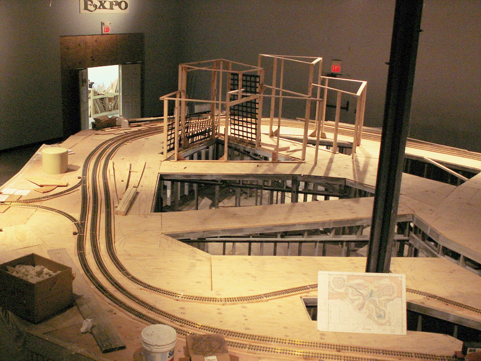
Once the street structure was completed, we could begin construction of the supports for the building facades (Figure 5). The design concept called for “permanent” support structures with removable, and in some locations movable, facades mounted to them.
 |
| Figure 5 The Beginnings of the Hotel Structure, 25 Feb 2008 |
We explored several techniques for building the facades which would be attached to the structures. The beginnings of the facades for the hotel are the grids shown leaning against the building structure in the center of Figure 6.
 |
| Figure 6 Building Support Structures and Beginnings of the Facades, 30 Apr 2008 |
Building the structures and facades was not very hard or complex, but it was time consuming. Constructing them for all of the buildings needed in the city would take much longer than the time we had until the intended opening day. Because of that, we explored other ways of making buildings. One of these techniques was used for the “capitol” building, which would be the focal point at the top of the main street. It was made of half-inch thick standardized segments of Gatorboard glued together on edge with hot glue to form the walls and window openings. Embellishments of dowels for columns, plastic bowls for the domes, and commercial plastic windows completed the look (Figure 7).
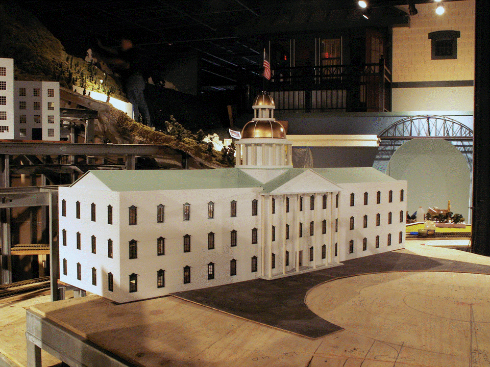 |
| Figure 7 The “Capitol” Building, 28 Jun 2008 |
Because more buildings were needed in a short period of time, we expanded the technique of using printouts of computer-assembled images of complete building exteriors, including walls, windows, doors, and storefronts. These were printed for us by Watson’s onto large (4’x4.5’) decals which we then laminated onto 3/16” Gatorboard using a laminating machine also available at Watson’s. We connected these façade boards at their vertical edges creating the building corners. These were sufficiently sturdy and rigid to stand up on their lower edges and support themselves, and needed only to be fastened in place onto the layout tables. The first full building we assembled using this technique is shown in the foreground of Figure 8 surrounding the support column.
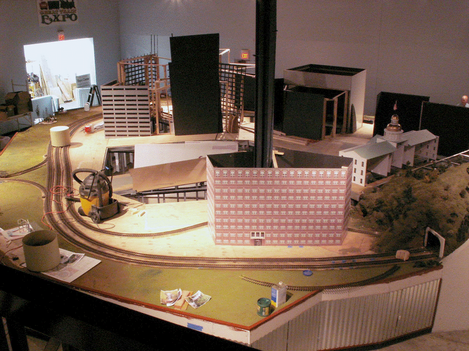 |
| Figure 8 The First Printout-Gatorboard Façade Building, 4 Jul 2008 |
Scenery (spray foam and ground foam) was added to the area between the aisle and the tracks going around the city by the Cincinnati volunteer crew. This area had always been envisioned as a park and one of the Cincinnati volunteers constructed a beautiful park, complete with trails, a playground, an ice cream stand, a dog park, and a lake (Figure 9) in the area adjacent to the parking lot for what will eventually be the main subway station at the bottom of the main street.
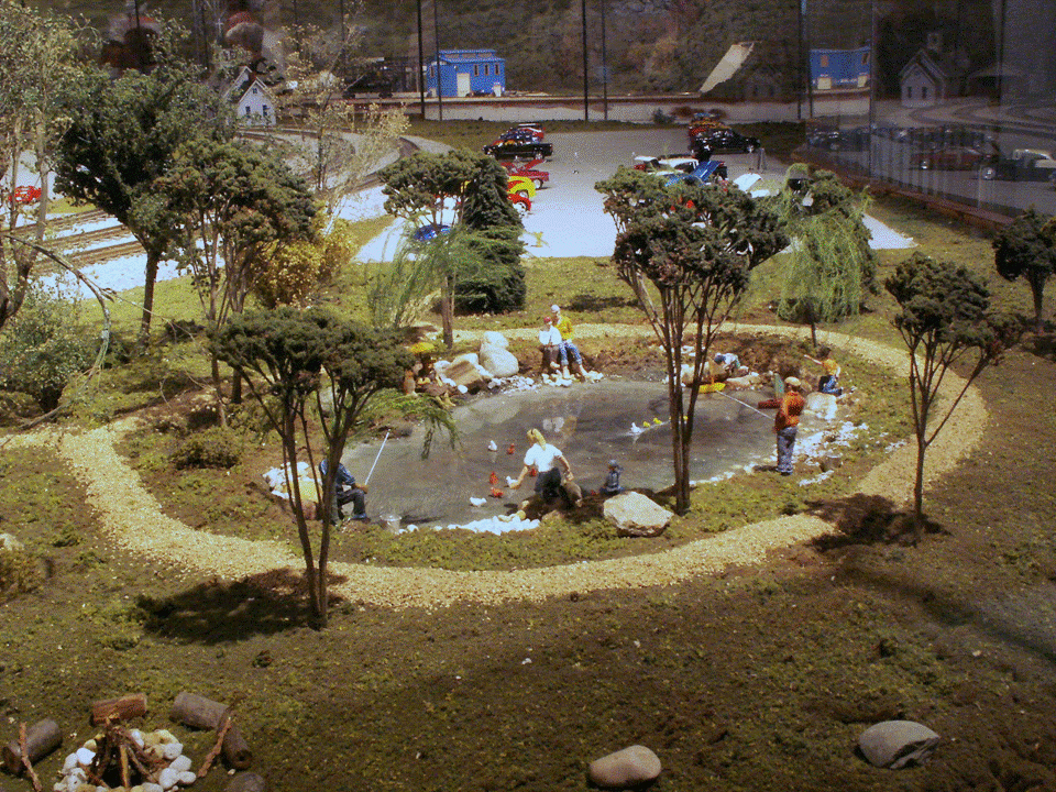 |
| Figure 9 The Park between the Aisle and the Tracks, 15 Jul 2008 |
Another method of using the computer printout decals was to apply them to sheets of plastic-coated Masonite. Unfortunately, the Masonite sheets tend to warp and require framing to force them to be flat. The framed Masonite facades were used for the hospital shown in the center of Figure 10.
 |
| Figure 10 The Post Office (Left) and Hospital (Center), 18 Jul 2008 |
The final façade technique we used was to glue reflective plexiglas sheets to ½” Gatorboard to get sufficient stiffness, mark the divisions between the simulated glass panels with automotive striping tape, and mount the resulting panels to the support structures. Figure 11 shows the results of this — the blue bank building in the center of the picture. Also shown (on the right) is the grid-type facade (assembled from 3/16” Gatorboard) with its green curtains, which were made from color Xerox copies of a computer-generated and colorized image. This is the hotel, “The Carlson of Oakmore,” named in honor of Gordon Carlson, one of our Dayton team members, who did the lion’s share of the work on these facades.
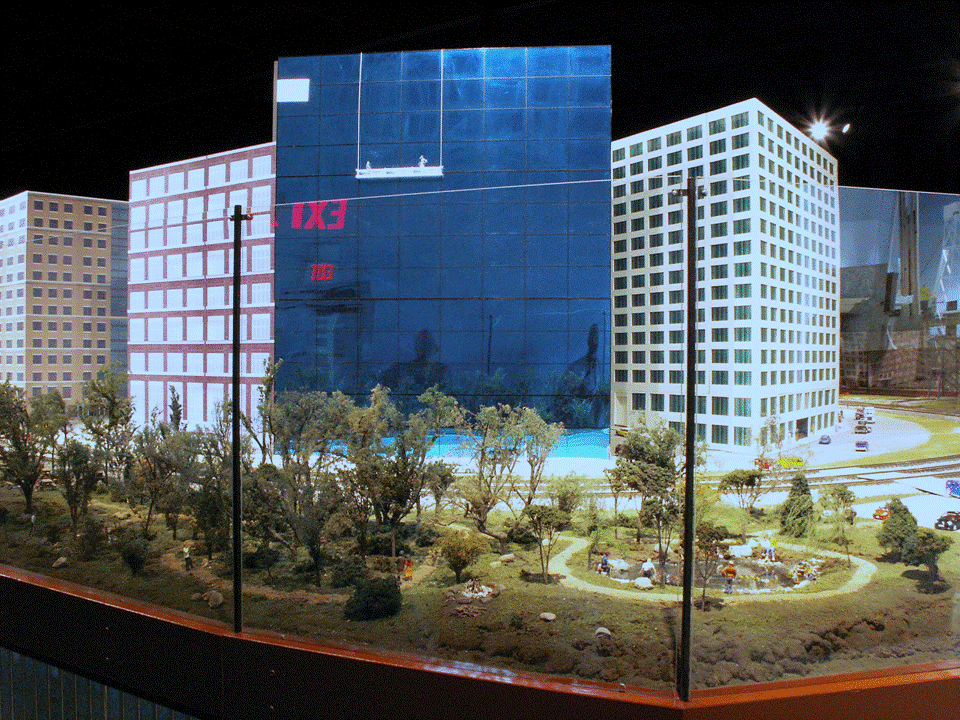 |
| Figure 11 The Blue Reflective Bank (Center) and Hotel (right), 30 Jul 2008 |
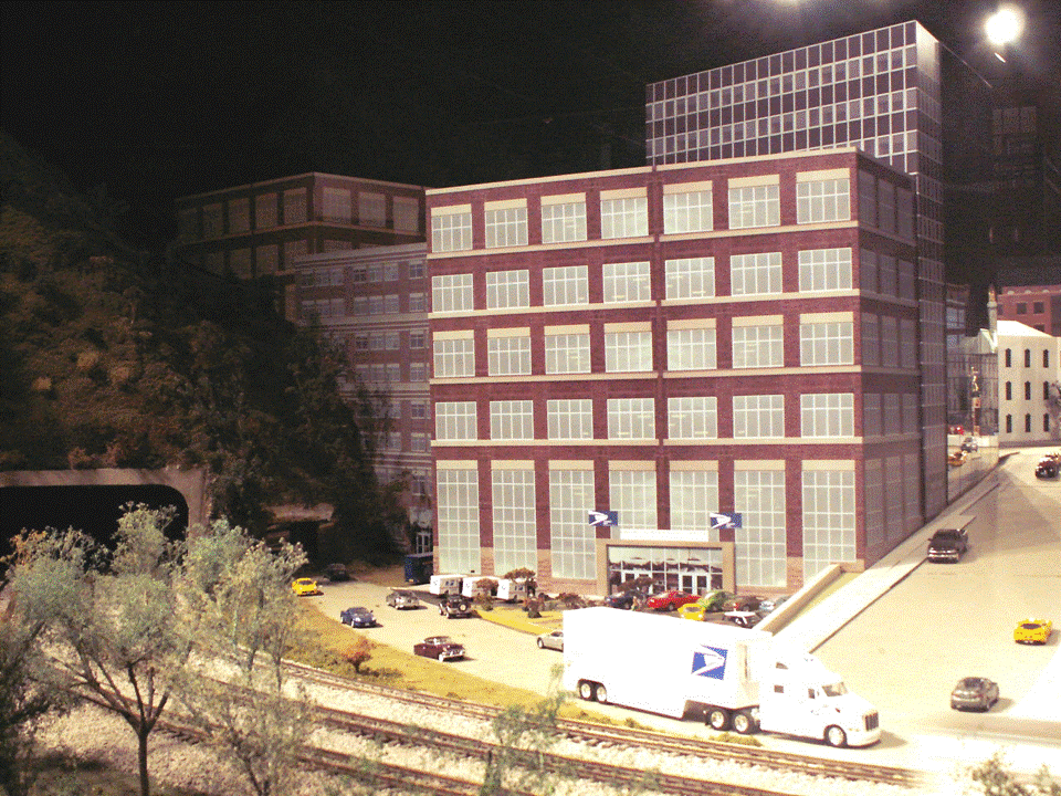
By the time the formal opening day arrived on 1 August 2008, we had put up facades for all of the buildings along the front street running just inside the loops of tracks. We also had facades installed temporarily at least part way up each of the streets successfully hiding the uncovered holes and the building support structures from viewers in the aisles. The view in Figure 12 was taken from the observation tower, which is not normally accessible to the public. It gives a good idea of the magnitude of the building effort we completed in time for opening day, in such a short period of time. It also shows some of the incomplete areas which were carefully hidden from the customers.
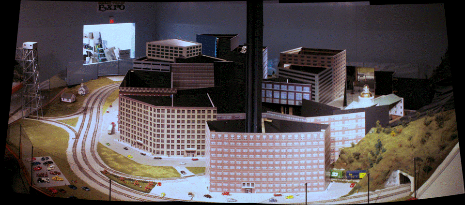 |
| Figure 12 The Modern City on Opening Day, 1 Aug 2008 |
Opening day, of course, didn’t stop us from continuing our work on the city. We next completed the two reflective buildings on either side of the “capitol” (Figure 13). We added the traffic circle and fountain at the top of the main street (Figure14). We added building details to make them look more three-dimensional and put in additional facades to hide the edges of the city at the hillside (Figure 15). And, we added a Christmas/winter scene including houses, a church, and a gazebo with Christmas decorations and an ice skating pond, complete with skaters (Figure 16). Other improvements included better-looking sidewalks, a couple of tunnel portals, and an eclectic collection of cars parked in the parking lot at the bottom of the main street, including taxicabs and a policeman munching on a donut.
 |
| Figure 13 , 20 Oct 2008 |
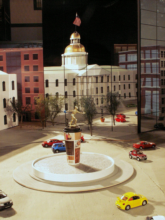 |
| Figure 14 , 17 Nov 2008 |
 |
| Figure 15 , 24 Nov 2008 |
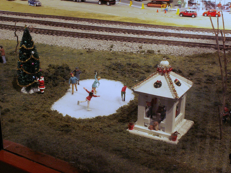 |
| Figure 16 , 1 Dec 2008 |
That finished our near-term work on the Modern City. Though there’s still much to do to make it better, it looks pretty good for now, and there are other higher priority needs on the layout. We chose to leave it as it currently is for a while so we could concentrate on the other areas which needed a lot more work, primarily the Middle and Modern Era engine and car servicing facilities.
Next month I’ll show you the development of the other of the two cities, the Middle Era city, with its Art-Deco style and nostalgic features which are quite familiar to some of us (at least to some of us older folks). Stay tuned!
© 2009 Tom Bartsch
MVGRS Big Train Project Coordinator